


Home Site Map - Techniques - Structure -
Carnation Walling - Slab Markout
![]() Mark the slab with a felt pen as per your CAD drawings to show
concrete reference and tie rod positions.
Mark the slab with a felt pen as per your CAD drawings to show
concrete reference and tie rod positions.
Mark outer edge of wall concrete
The OUTER edge of the WALL CONCRETE is the reference and this needs to be as per your house CAD drawings. This is the INNER face of the EPS. The EPS outer edge cannot be used as a reference because it overhangs the concrete slab.
Using batterboard strings and a plumb-bob, accurately mark the corner positions of the outside of the wall using a sharpie felt pen on the concrete slab. Initially just use small cross marker pen marks just in case as some tweaking will be needed. (For upper floors, the term "slab" refers to the top of the concrete floor of the house level beneath.)
Using a laser measurer, measure the length of the rectangle sides and diagonals. Use a home made laser target at the far side. Measuring the diagonals allows you to check the rectangle has exactly square corners. The diagonals need to be exactly the same and the distance should also be the exact measurement that your CAD drawing says it should be (if not then find out what's wrong before proceeding).
The base of the laser measurer goes on the marked cross.
Draw lines (red on the drawing below) on your AutoCAD drawings corresponding to the measured distances. This takes a bit of moving around the lines to get them to resolve to all the measurements. From this you will be able to see what adjustment to the corner points is needed.
Mark on the slab in a different color (eg red) the adjusted corner cross positions.
The outer edge of the wall concrete (inner edge of the EPS) is an important reference line, and everything is based off that, so it needs to be accurate.
Hopefully the wall rectangle will also properly relate per the CAD drawings and with where the key notch has been formed in the slab.
For internal walls, the outside wall concrete is the concrete edge furthest from the building center.
Draw lines all the way for concrete outside
Join up the corner markers with long straight lines. I do this by setting a vertical line from a self leveling laser. At night in the dark, make marker pen marks in the path of the laser and then join them up with a long ruler.

Draw lines for concrete inside
Even though not a fundamental requirement it is good to also draw the edge of the inside of the concrete as it will let you see and remember which walls are 12" concrete vs 8" concrete. Also draw the concrete outline of any internal support pillars.
Kicker lines
The kicker planks are 3.25" wide. That specific width is so that the inner edge corresponds with the wainscoting. The position of the inner kicker planks depends on whether it is an 8" concrete wall or a 12" concrete wall at each particular location.
The inside face goes 1.5" towards the center of the house relative
to the edge of where the plywood will be (the plywood edge closest to the
inside of the house). Relative to the sharpie felt pen drawn reference
line the distance of the edge of the kicker board that is closest to the
center of the wall is...
Wall concrete
thickness (8" or 12") + 1/4" (thin ply) + 1/2" (thick ply) + 1.5"
(vertical 2x4s)
For an 8" cavity wall the distance is 10-1/4"
(14-1/4" for a 12" cavity).
Note that the plywood sheets are actually slightly thinner than the nominal thicknesses. This means that the concrete is marginally thicker than the 8" (or 12"), but only by 1/16" + 1/32" = 3/32" so it is of no consequence.
Mark kicker line on slab
Mark the position of the inner line accurately with a felt pen (joining up your measured marks with a long ruler). Check that this accurately relates to the CAD drawing and that you haven't accidentally made it an 8" cavity where it should have been 12".
For internal walls, you will add nailed down kicker boards on both the outside and inside of the wall.
To provide for slab height variations and provide lots of strength, the kicker planks are a nailed down 1.5"x3.25" with a marked and drilled 1.5"x3.25" screwed on top.
Colored marker pens fade quickly in sunlight so you may need to go along the line with a black pen in dashes (see picture below).
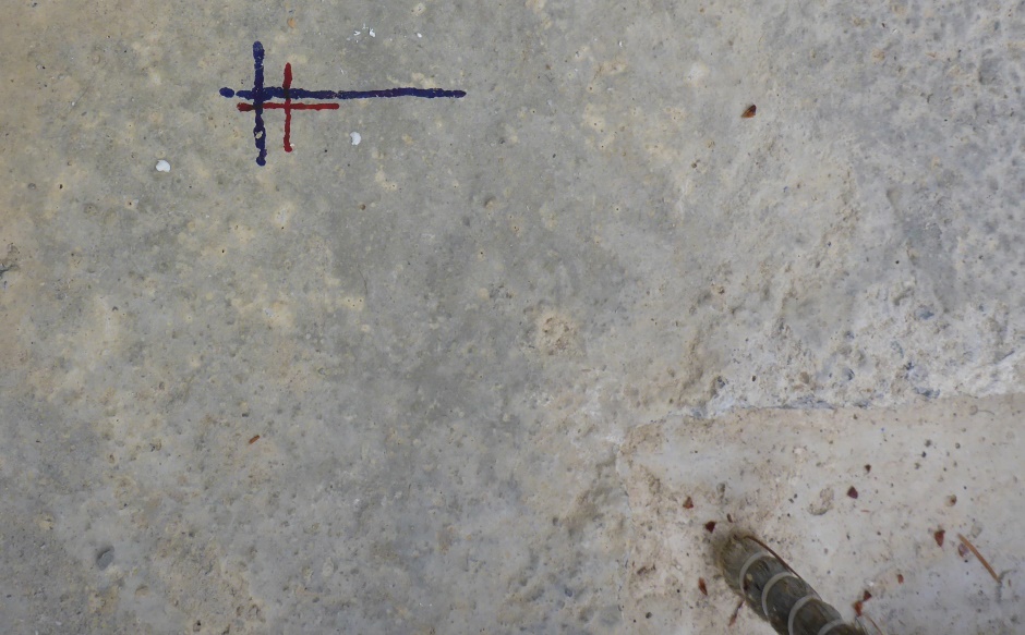
Mark tie rod positions
The positioning of the EPS sheets and bracing is all done from the convex corners of the wall concrete reference line. You work away from the corner until you get to either the center divider point of the house or a concave corner.
Mark with a sharpie felt pen along the outside of the wall concrete the points where the quadrant divider cross line intersects with the wall. These points should also of course be on your CAD drawing.
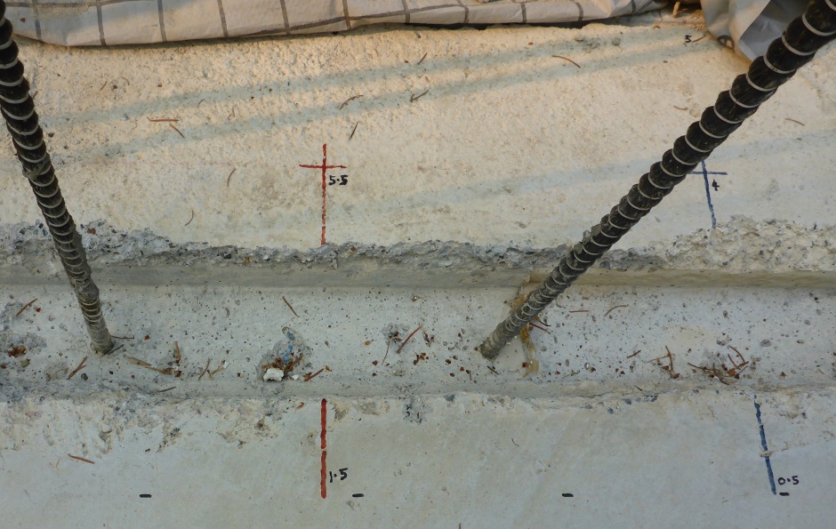
Measuring from the convex corners of what will be the outside of the wall concrete (ie the reference line), put a felt pen mark every 1 foot. Make the even numbered ones (the primary ones) one color (I use red). These are 0, 2, 4, etc. Make the odd numbered secondary points a different color (I use blue). These are 1, 3, 5, etc. The marks give the positions of the wall ties that go through the concrete and the possible positions of EPS (and plywood) joins (minus 1 inch). The marks should exactly mimic the marks on your CAD drawing.
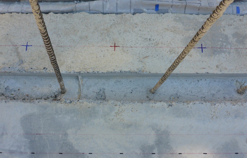
At corners in the case of joining to 12" cavity walls it is necessary to adjust the wall tie placement by 4" relative to the 1' regular grid. Again this should be shown on your CAD drawing.
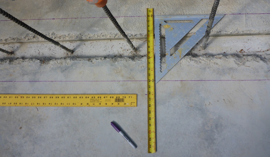
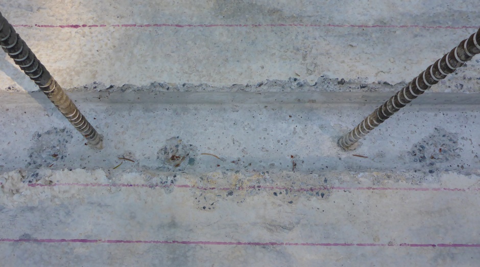
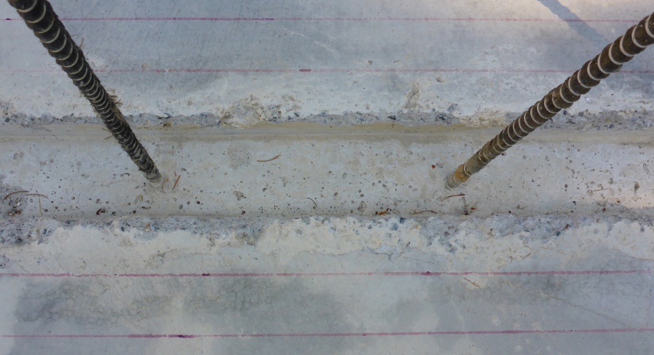
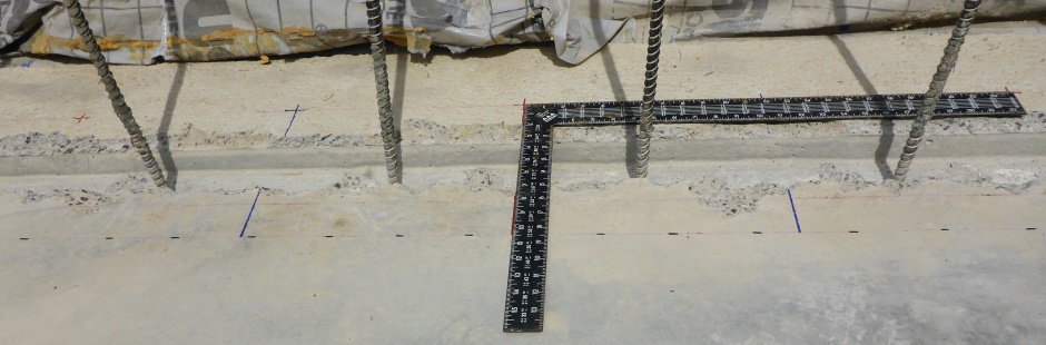
Draw orthogonal lines at tie places
At both the primary and secondary tie positions, draw red and blue lines from the outside line to the kicker edge line. These lines are useful to help get the screw down kicker boards in the right position.
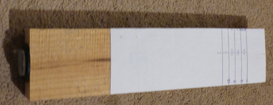
Marking slab heights
In practice your slab will not be 100% level. You will likely have got some idea of where the high spots are from when you flooded the slab for the concrete curing. The highest point on the slab will be designated the slab height reference and all other points on the slab will use shims to get to that height.
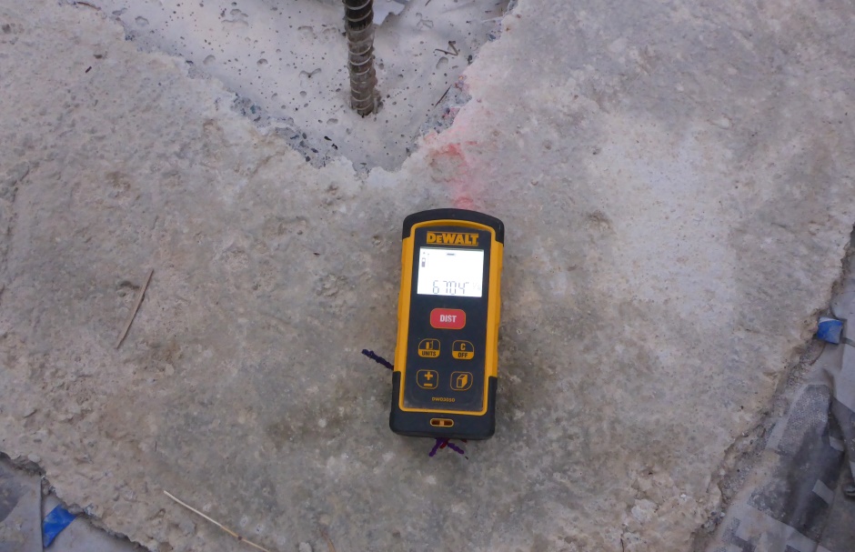
Use a Self leveling laser on the slab in the center of the building. The beam will be something like 2" off the surface of the slab. It is worth marking the exact center of the building on the slab so you have a consistent place for the laser. Manually rotate the self leveling laser as needed and measure the distance from the beam to the surface of the concrete to find the shortest measurement, ie where the concrete is highest.
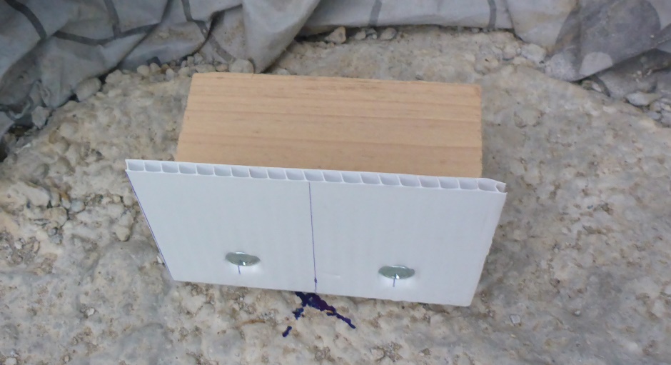
Use a 1 foot long piece of vertical 2x4 with white paper glued on as a laser target. Position a bubble level on the top to help you hold it vertical. As you try different places on the slab, make a small pencil mark on the stick to show the highest point found so far (which will be the lowest mark on the target).
Check all three points along the tie rod line when looking for the
highest point. The positions are...
1-1/2"
beyond concrete inner edge
3/4" within
concrete outer edge
6" beyond concrete outer
edge (edge of slab)
Mark all 3 heights at all tie rod positions
The lowest pencil mark on the target (that therefore corresponds to the highest point on the slab) is designated the reference. Make numbered 1/8" marks up from this so you have a measuring ruler.
At each 1 foot tie rod marker round the outside concrete edge in all three positions (given above), write the height offset on the slab using a number to represent the number of eights of an inch that it is below the highest point, eg if it is 11/16" below the ref height then write 5.5. Do both the primary (red) tie rod positions and the secondary (blue) positions too.