


Home Site Map - Steps - Foundations -
Foundation Rebar - Horizontal Rebar
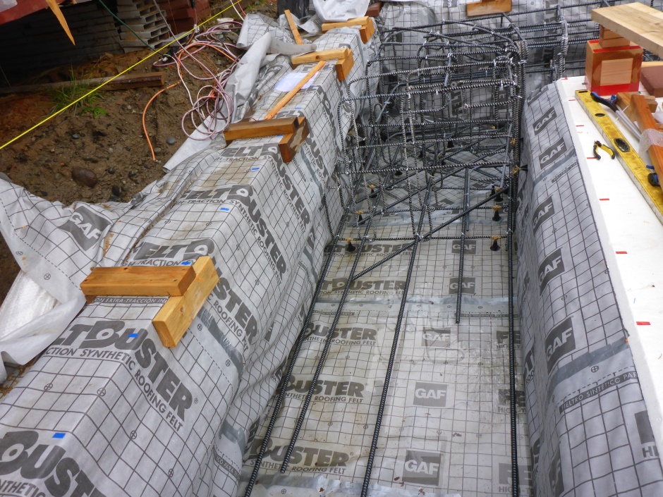
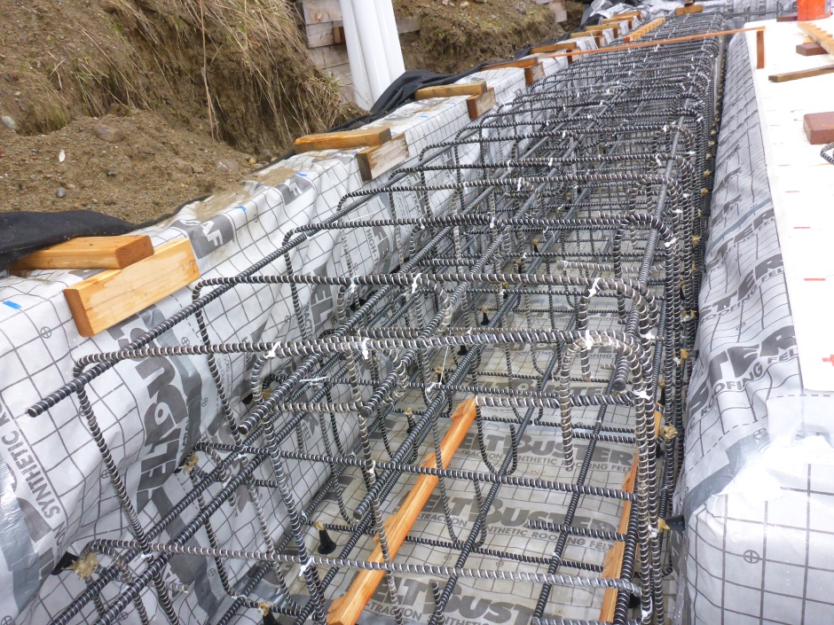
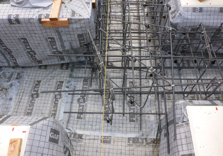
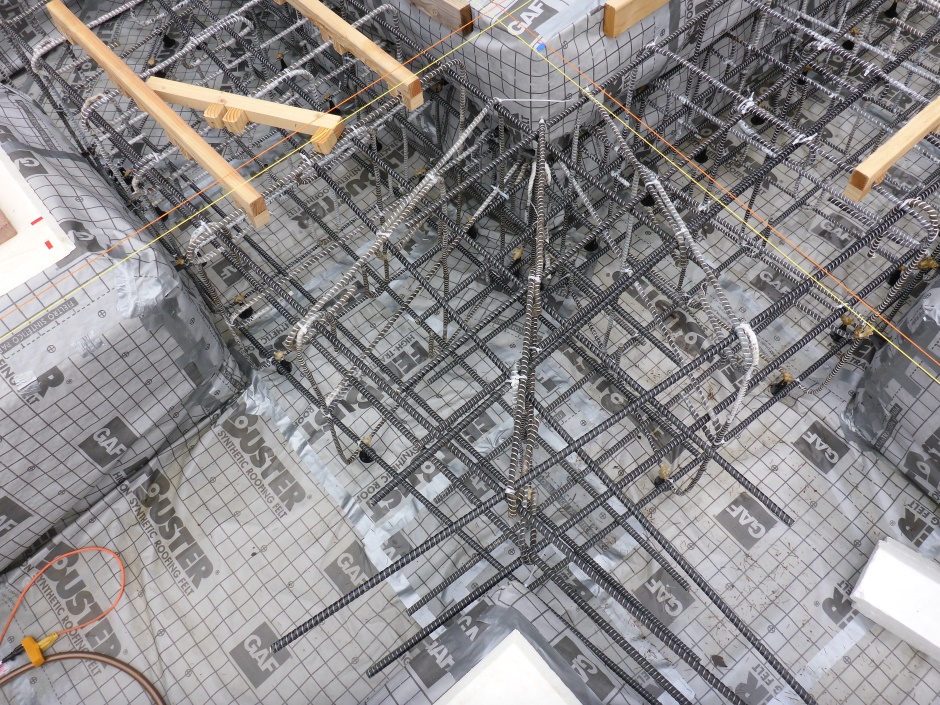
![]() Rebar is threaded horizontally through the rebar stirrup assemblies
that are every 1 foot along the trenches.
Rebar is threaded horizontally through the rebar stirrup assemblies
that are every 1 foot along the trenches.
Horizontal rebar
Cutting horizontal rebar
Typically in a trench for each horizontal position will be one uncut length and one cut length. It is good to work out the cut lengths in AutoCAD so they don't have to cut them in situ.
Opinion and code varies, but at absolute minimum they must overlap by at least 22.5" (ie at least 30 times the #6 rebar diameter). I chose to make the overlap at least 3'2" (38") to be conservative. In the calculation for how long the cut piece should be, assume the 19'2" rebar straight only provides 16'.
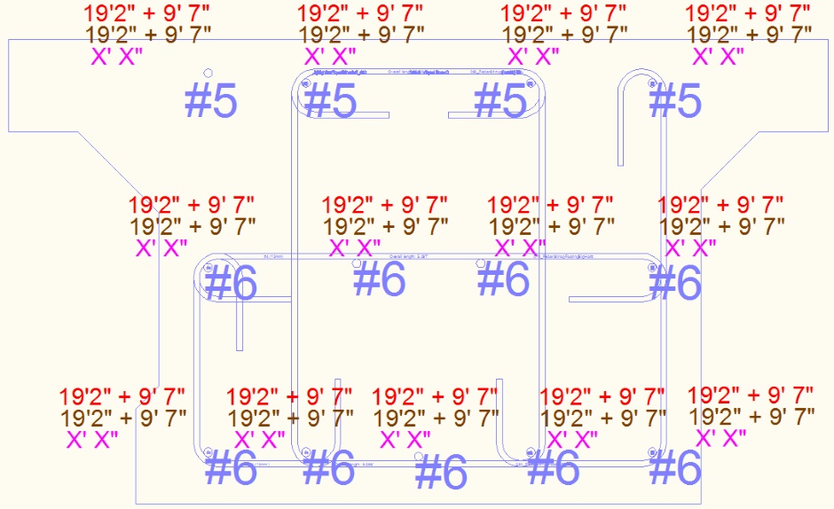
After calculating what the cut lengths need to be, use some judgment to increase the overlaps to avoid waste given that there is no point in having a bunch of little offcuts. Sometimes increasing the cut length to 19'2 (and thus avoiding cutting) is the right thing to do. Sometimes increasing the cut length to 9'7" (ie half of 19'2") is the right thing. These rounding ups make particular sense where the extra can extend into internal wall areas.
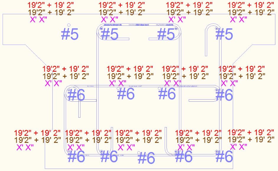
For each footing trench make a drawing to show the lengths of horizontal rebar required in each trench. The red figures give the figures that were decided on.
Furthest west (and the furthest east) north-south footing (2 off)
East-west corners (4 off)
Portico north-south short edges (4 off)
Portico east-west long edges (2 off)
Internal north-south long walls (2 off)
Internal east-west short portico walls (2 off)
Overall cut list
If you want to you can do all the cutting in one go prior to moving the rebar to the appropriate places. You can form an overall cut list. It is also worth listing the uncut 19'2" lengths to help with moving logistics.
#6 rebar
19' 2" (2 x 13) + (4 x 0) + (4 x 9) + (2 x 9) + (2 x 18) + (2 x 9) = 26 + 36 + 18 + 36 + 18 = 134
14' 2" (2 x 2) + (4 x 0) + (4 x 0) + (2 x 0) + (2 x 0) + (2 x 0) = 4 = 4
13' 0" (2 x 1) + (4 x 0) + (4 x 0) + (2 x 0) + (2 x 0) + (2 x 0) = 2 = 2
11' 0" (2 x 2) + (4 x 0) + (4 x 0) + (2 x 0) + (2 x 0) + (2 x 0) = 4 = 4
9' 7" (halving) (2 x 0) + (4 x 9) + (4 x 0) + (2 x 4) + (2 x 0) + (2 x 9) = 36 + 8 + 18 = 62
6' 2" (offcut) (2 x 0) + (4 x 0) + (4 x 0) + (2 x 1) + (2 x 0) + (2 x 0) = 2 = 2
5' 0" (offcut) (2 x 0) + (4 x 0) + (4 x 0) + (2 x 2) + (2 x 0) + (2 x 0) = 4 = 4
#5 rebar
19' 2" (2 x 5) + (4 x 0) + (4 x 4) + (2 x 4) + (2 x 8) + (2 x 4) = 10 + 16 + 8 + 16 + 8 = 58
114' 2" (2 x 1) + (4 x 0) + (4 x 0) + (2 x 0) + (2 x 0) + (2 x 0) = 2 = 2
13' 0" (2 x 1) + (4 x 0) + (4 x 0) + (2 x 0) + (2 x 0) + (2 x 0) = 2 = 2
11' 0" (2 x 1) + (4 x 0) + (4 x 0) + (2 x 0) + (2 x 0) + (2 x 0) = 2 = 2
9' 7" (halving) (2 x 0) + (4 x 4) + (4 x 0) + (2 x 1) + (2 x 0) + (2 x 4) = 16 + 2 + 8 = 26
6' 2" (offcut) (2 x 0) + (4 x 0) + (4 x 0) + (2 x 1) + (2 x 0) + (2 x 0) = 2 = 2
5' 0" (offcut) (2 x 0) + (4 x 0) + (4 x 0) + (2 x 1) + (2 x 0) + (2 x 0) = 2 = 2
Personally I tend to just cut the rebar to the right lengths as I need it.
Add horizontal rebar
Add bottom horizontals
Start by adding the #6 rebar straights in the bottom locations for the current end of the trench. Cable tie the ends to the corner assemblies. They end with 1" on overlap over the corner 45 degree pieces.
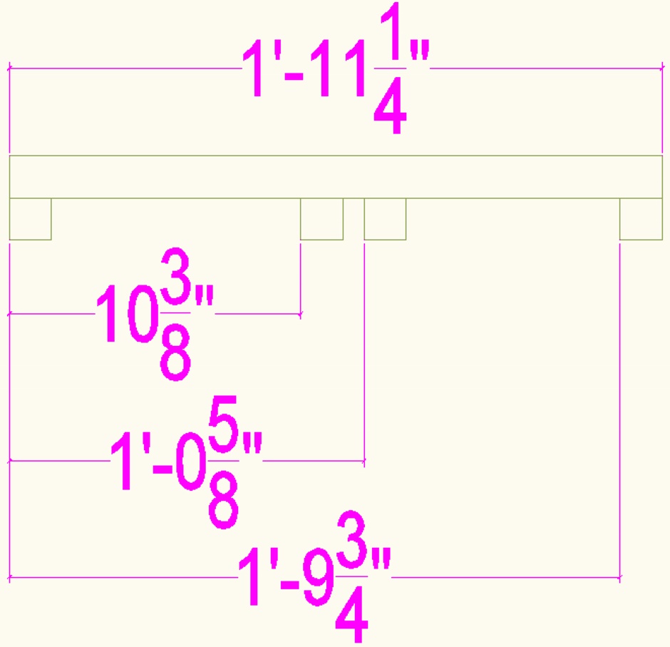
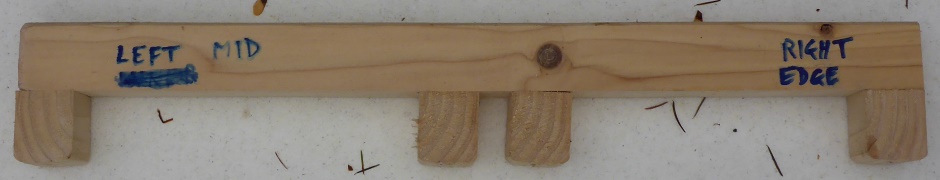
Four of the five positions are obvious on the stirrup assembly. Use a wooden measuring stick to set the position of the fifth one.
Note that typically at each location the horizontal is actually made up of two pieces to get the necessary length. It will be one full length piece and one shorter cut piece. Alternate which end of the trench gets the long pieces and which the short. As there are 5 bottom locations, make the two outer locations (and the middle location) be the full length pieces.
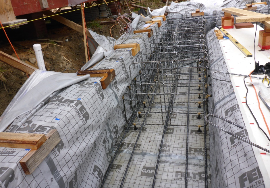
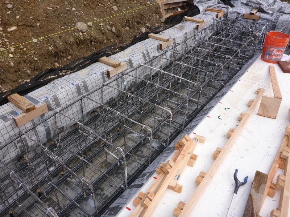
Add stirrup assemblies (of the correct variant for that section of footing) into the trench one at a time by threading the bottom horizontals into the assembly and then work the assemblies along the trench until they are in the right locations as indicated by the colored tape positions.
You want some membrane slack above the side chairs and some below.
Slide the rebar assemblies in at an angle with the horizontal rebar chairs held in the right place with your hands so they don't break. Make sure you are not pulling the foundation linings out of their correct position and make sure there is equal slack in the linings on both sides of the trench (and above and below the horizontal chairs).
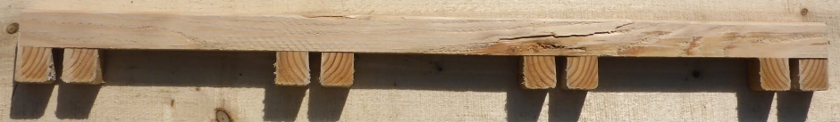
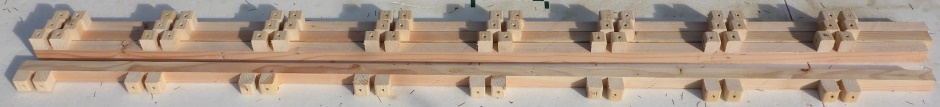
Set the correct position of particularly the bottom of the stirrup assembly using a 4' long wood jig with notches one foot on center (5/8" wide notches).
Cable tie the two outer bottom horizontals to the bottom corners of each stirrup assembly. This will hold the stirrup assembly in its right location. Note that it is good that we are only tying the bottom of the stirrup assemblies because it allows some adjustment of the top when later adding the vertical rebar. For the moment the stirrup assemblies will stay approximately vertical because of friction with the side chairs against the footing sides.
If you find they are flopping around then you can use 8' long wooden notch sticks to temporarily hold the tops of the stirrup assemblies.
Note that many of the footings span across the building center cross and as such the variant of stirrup assembly used will change half way along the trench.
When you get about half way along the length of the footing, add the second lengths of bottom horizontal rebar in the right locations (alternating long and short). Initially you can push it well into the trench length to keep it out of the way.
When you get about three quarters of the way along the footing, cable tie the second lengths of horizontal bottom rebar in the right locations such that they will overlap by about 1" what will be the 45 degree corner piece at the forthcoming corner.
Add other horizontal rebar
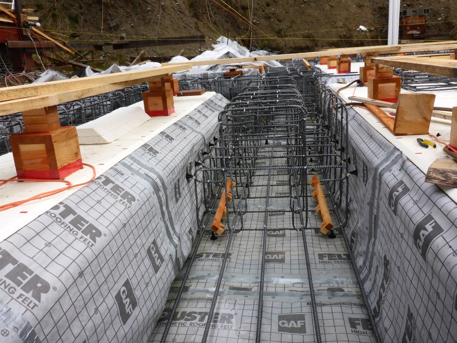
Also at about three quarters of the way along, add all the other horizontal rebar, both the full length and the cut shorter length pieces. It needs to all be in the right general locations relative to the stirrup assembly rods, but it does not matter if it droops down. Initially push it all as far in as it will go to keep it out of the way. Make sure the ends of the rebar do not risk puncturing the membranes. Also when feeding it in it is good to use a plank of wood to protect the edges of the footing at the end. It is ok to bend the rebar to get it in as it will happily spring back.
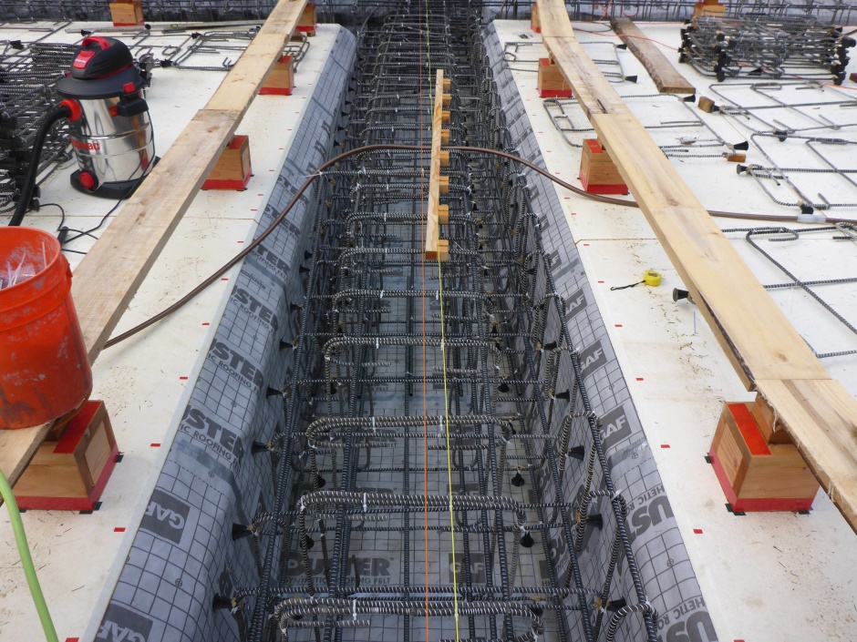
Once all the stirrup assemblies have been added to the footing trench the middle and upper horizontal rebar can be cable tied in the correct locations from above. Lay a plank across the trench and lay on it to allow you to reach down into the trench.
Internal wall footings
The same basic techniques are used with the internal wall footings.
Internal cross corners
Where internal wall footings meet external wall inner corners are a little complicated because of the 8" offset and the need for angled stirrups.
At the cross points where and external footing meets an internal footing there is lots of crossover for the horizontals from one trench with the horizontals from the other trenches. Because of this there is no need for angled horizontal bars.