


Home Site Map - Techniques - Automation and Data -
Home Automation - PC Input Output
![]() How to provide inputs and outputs on a PC using a USB connection.
How to provide inputs and outputs on a PC using a USB connection.
Talking to power control modules is done using the Hub described above, but there is also a need for sensor inputs and some digital outputs from the PC. This is best done using primarily low voltage wiring and modules.
You need a interface boards that can convert USB from the PC to digital outputs and sensor inputs. My choice is to use Phidget modules. They are more expensive than I would like but they are easy to use.
Installing Phidgets libraries
http://www.phidgets.com/docs/OS_-_Windows#Quick_Downloads http://www.phidgets.com/docs/Language_-_C_Sharp#Documentation http://www.phidgets.com/docs/1014_User_Guide
Phidgets Hub IO Modules
Hub
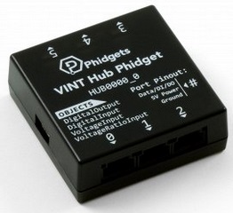
https://www.robotshop.com/en/vint-hub-phidget.html $30 free shipping
https://www.phidgets.com/?tier=3&catid=2&pcid=1&prodid=643 $30 + shipping
Digital inputs (VINT)
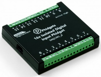
https://www.robotshop.com/en/phidget-vint-16-isolated-digital-input.html $37.50 free shipping
https://www.phidgets.com/?tier=3&catid=2&pcid=1&prodid=625 $50 + shipping
Digital outputs (VINT)
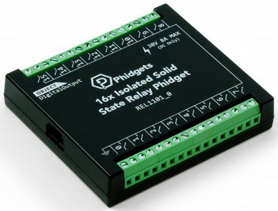
https://www.phidgets.com/?tier=3&catid=46&pcid=39&prodid=721 $50
8A 30VDC
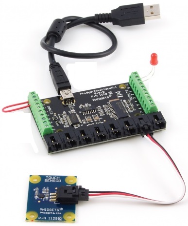
Inputs and outputs (USB)
This is the old Phidget way of doing things.
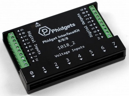
https://www.phidgets.com/?tier=3&catid=2&pcid=1&prodid=1021 $80
https://www.phidgets.com/?tier=3&catid=57&pcid=50&prodid=540 $6 for plastic cover
Digital inputs (old)
The module provides 8 digital inputs to which you feed more than about 4.2 volts to designate a high and about 0 volts to designate a low. These are useful for things such as magnetic sensor switches and motion sensors.
The Digital Inputs have a Digital Input Hardware Filter to eliminate false triggering from electrical noise.
There are pull-up resistors on the digital inputs so you don't need a 5VDC power supply for switches. Just connect the other end of the switches to ground (which is the first screw terminal). Digital inputs are 5VDC (but can handle +/-15VDC). Threshold is 4.2V. http://www.phidgets.com/docs/Digital_Input_Primer
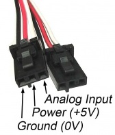
Analog Inputs (old)
The Analog Inputs are used to measure continuous quantities, such as temperature, humidity, position, pressure, etc. Phidgets offers a wide variety of sensors that can be plugged directly into the board using the cable included with the sensor. For more information about these inputs and their connectors, have a look at the Analog Input Primer. Sampling rates can be set at 1ms, 2ms, 4ms, 8ms and multiple of 8ms up to 1000ms.
Analog inputs are 5VDC (and no more). http://www.phidgets.com/docs/Analog_Input_Primer
Digital Outputs (old)
The Digital Outputs can be used to drive LEDs, solid state relays (such as the 3052 SSR Relay Board), transistors; in fact, anything that will accept a CMOS signal.
Digital outputs are 5VDC at 16mA. The module provides 5V on the terminal block next to Digital Output 7.
User guide: http://www.phidgets.com/docs/1018_User_Guide
Relay Board
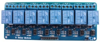
Adding this board to a the digital outputs of a Phidgets sensor board is a cost effective way of getting relay outputs.
http://www.amazon.com/gp/product/B00KTELP3I?psc=1&redirect=true&ref_=oh_aui_detailpage_o05_s00 $8.99
The relays are AC250V 10A ; DC30V 10A.
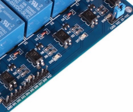
JD-VCC is used to power the relays. When the board is shipped, JD-VCC and VCC are jumpered together so that the VCC from the inputs side is used to power the coils on the relays. You will not want to try to use USB power to power the relays. Remove the jumper and use a separate 5VDC power supply brick for the relays. Connect the positive from the power supply to the JD-VCC pin and the negative to the ground pin.
Feed 5VDC directly from the Phidgets board for the logic circuitry (the pin next to digital output D7 on the Phidgets board) to the VCC pin on the relay board next to the control inputs.
These units energize when +5v is applied to VCC, then GND (+0v) is applied to the terminals. It's a bit counter-intuitive and annoying that +0v turns them on, and +5v turns them off, but that's how they work.
Solid State Relays
Instead of mechanical relays you can use solid state relays. They are more expensive, but depending on the application can be more reliable and can handle more current. You can connect them directly from the digital outputs on the Phidgets board.
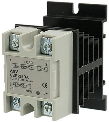
$8.50
http://www.phidgets.com/docs/Solid_State_Relay_Primer
Note that this does not give you light dimmer functionality - only on and off. It also looks like it has a minimum load requirement.
http://www.anv.com.tw/pdf%5Ccs-SSR.pdf