


Home Site Map - Techniques - Plot Infrastructure -
Drainage - Key Points
![]() Cutting through the boiler plate, here's a distillation of what is
actually required.
Cutting through the boiler plate, here's a distillation of what is
actually required.
Site general info
The drainage plan uses "Full dispersion".
The build site is 27,500 sqft.
New impervious: 8,979 sqft
Existing impervious: 4,488 sqft
After removing mobile home,
impervious since 2001 is 12,217 sqft.
Impervious after 2001 is
1.17% of site.
Keep the drainage ditch that goes down to the wellhouse.
Ideally
improve the dispersal trench on the end of it along contour.
Remove dispersion trenched to south east of mobile.
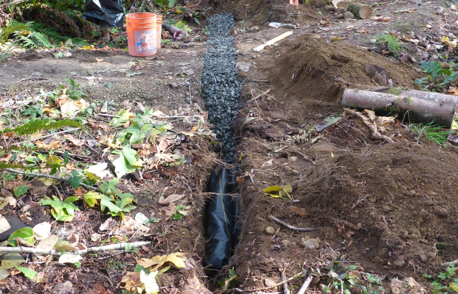
Dispersion trench
50 foot dispersion trench.
200 feet of native vegetated down from
that.
Rated capacity of the 50' trench is 10,000 sqft, so we have 1,021 sqft
for future buildings.
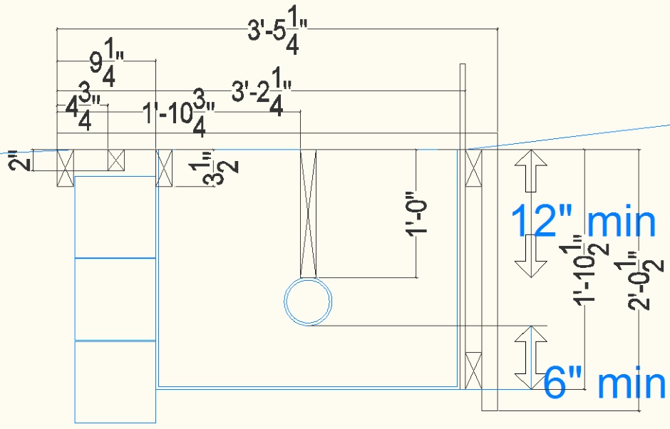
Trench is 23" deep (min) and 28.5" wide (min).
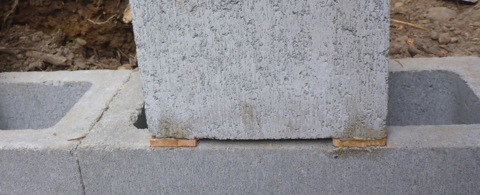
Grade board is specified as 2x12 pressure treated wood.
V shaped 2"
deep 2" wide at top V notches every 18".
Supported on 4x4 wooden
posts (not pressure treated).
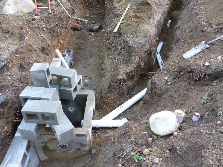
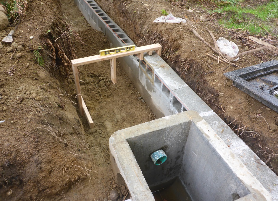
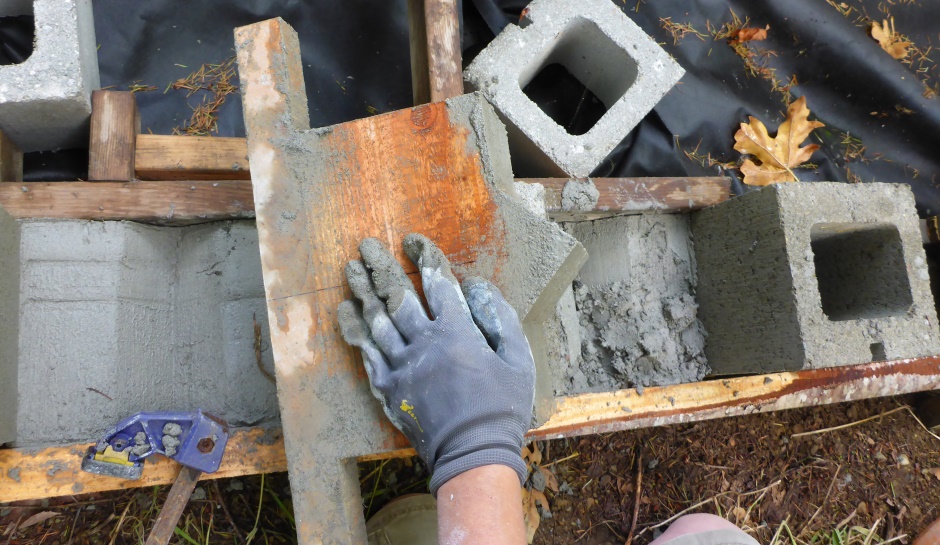
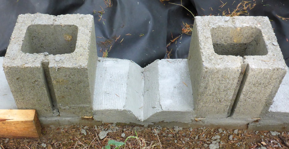
(I actually
implement the grade board using a small concrete wall.)
Trench filled with 1-1/4" crushed rock
(washed, no fines).
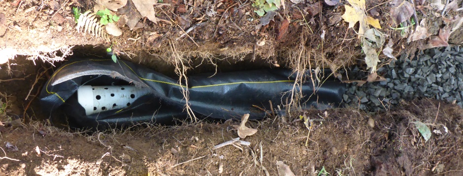
Trench lined with filter fabric.
4" perf pipe in
trench.
Top of perf pipe is 12" below surface.
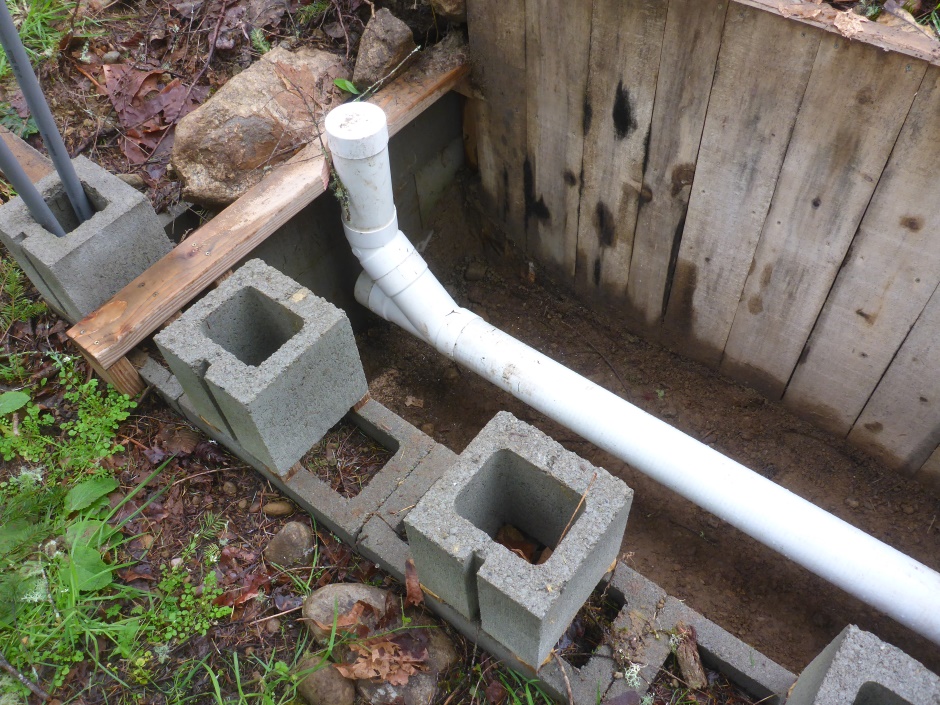
Cleanout Wyes at each end of pipe.
Caps at end of pipe.
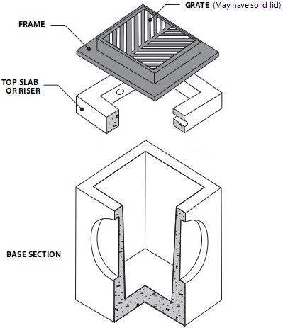
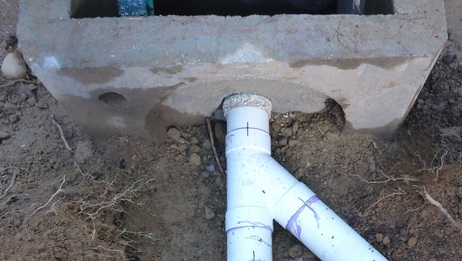
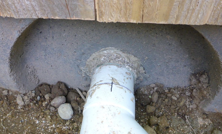
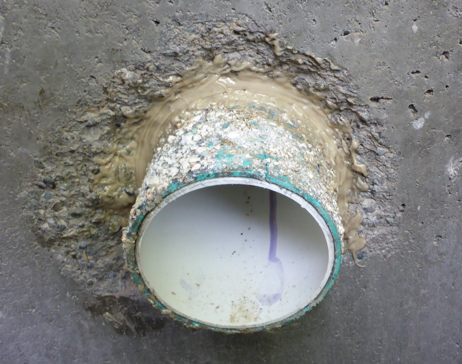
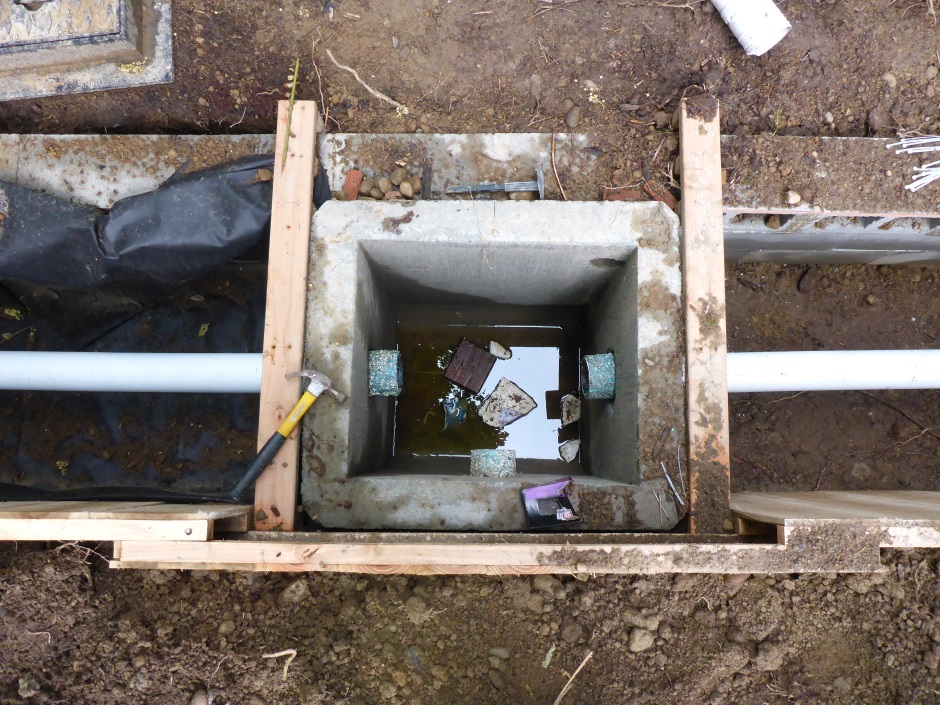
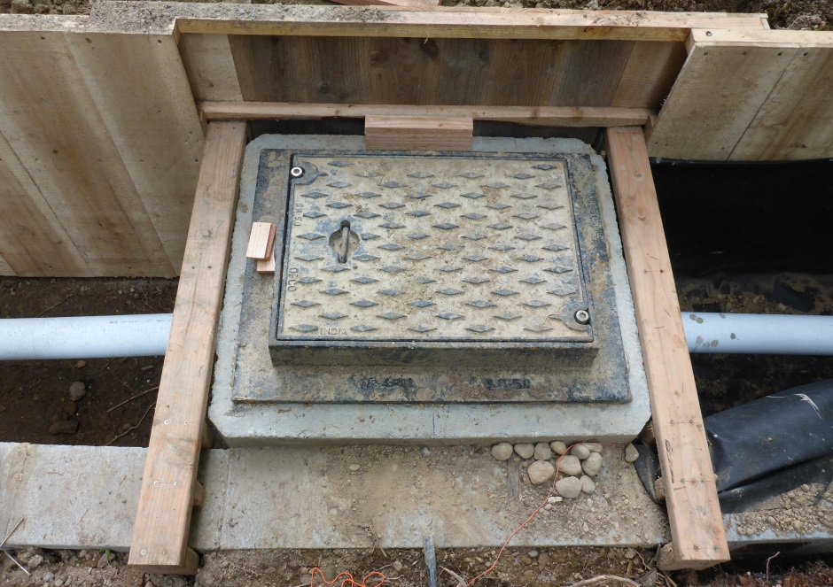
Water enters in the
middle using a "Type 1 Catch Basin with solid cover (locking)".
The water enters on a long face.
Need filters because it says the dispersion trench must not be
clogged by the construction process).
Implement the planned filter boxes.
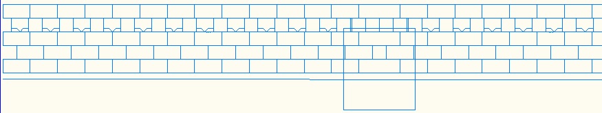
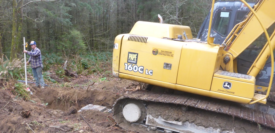
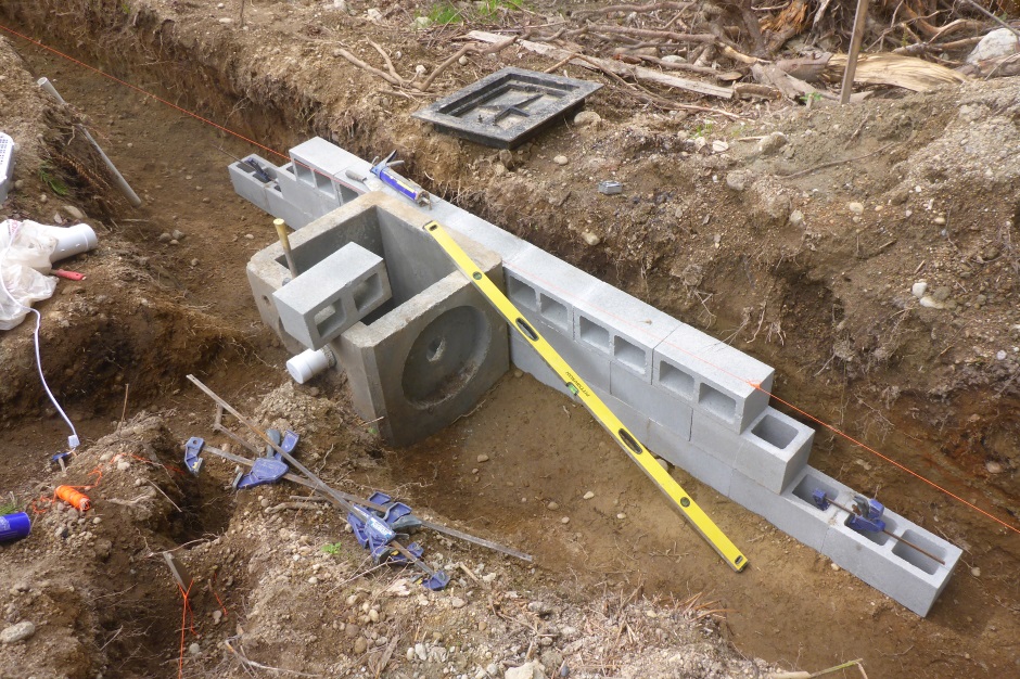
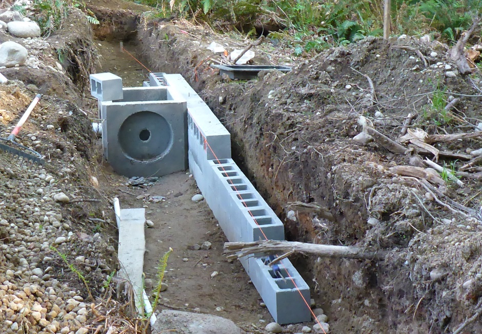
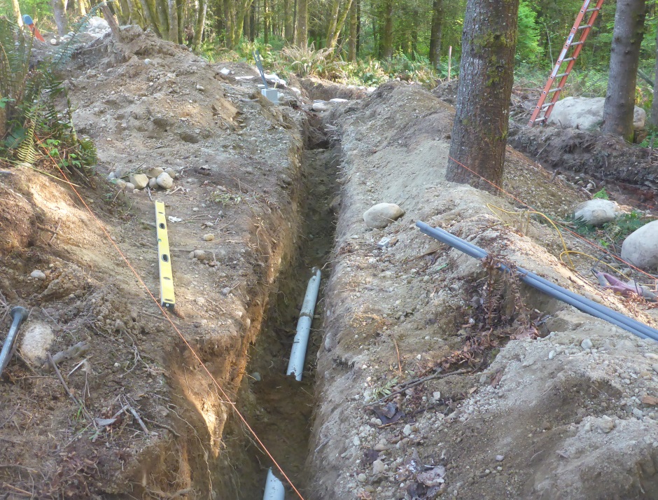
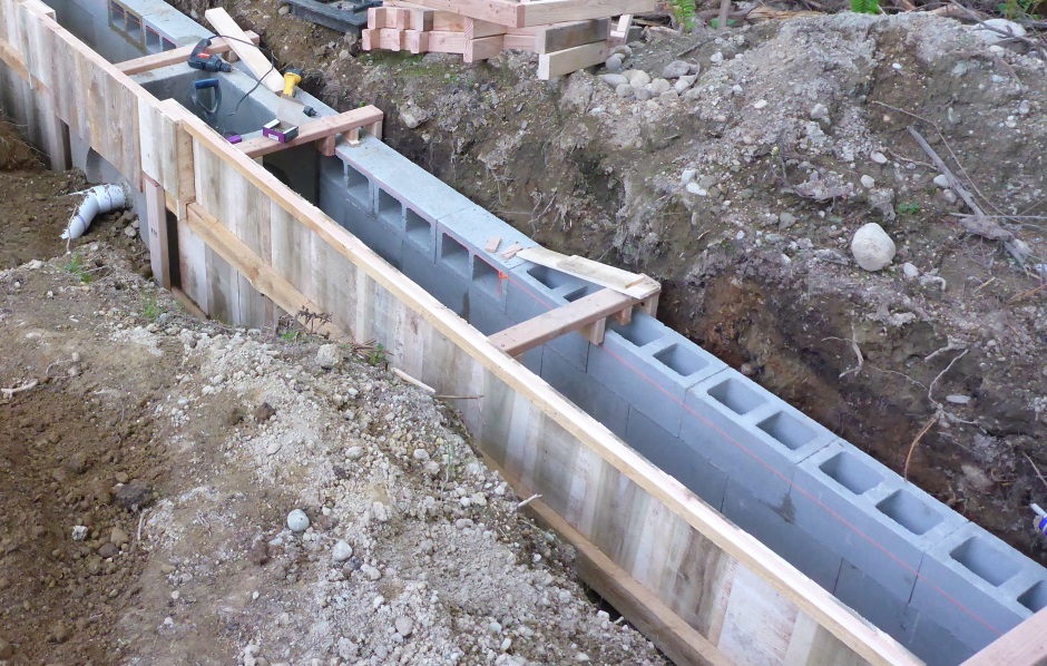
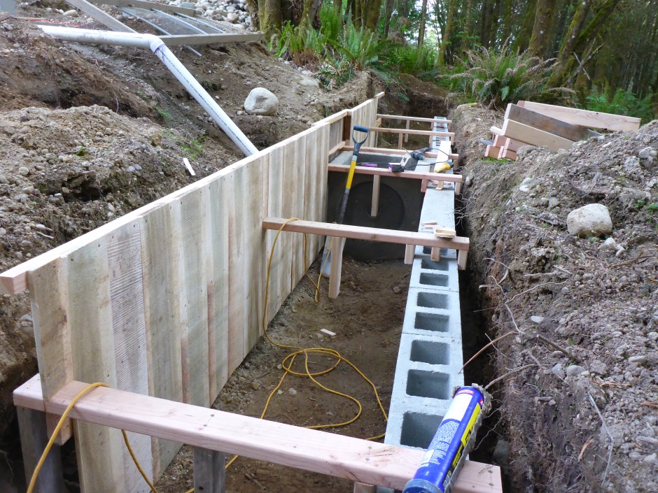
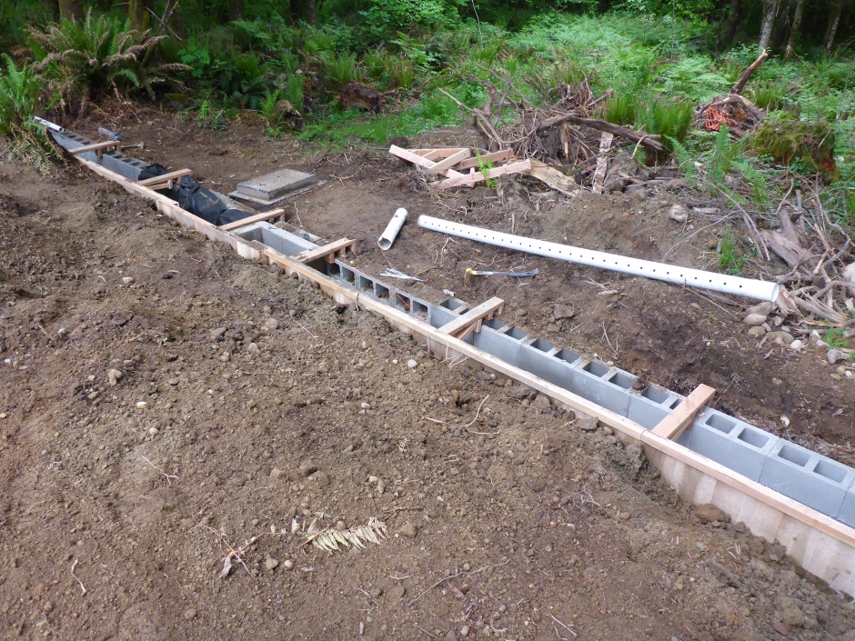
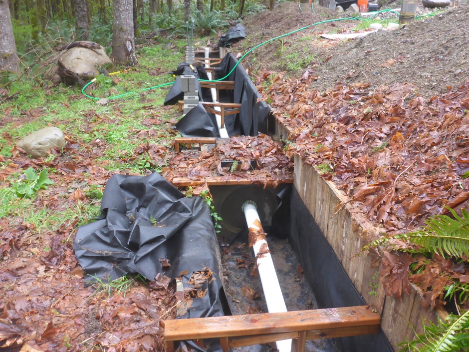
The ditch needs to be level, ie along the ground contour. The ditch only needs to be 2 feet deep, except where the catch basin goes. The ditch needs to be 3'2" wide. The top of the catch basin is at the top of the ditch. The top of the notched grade board is the top of the catch basin. The notched wall is against the outside of the catch basin.
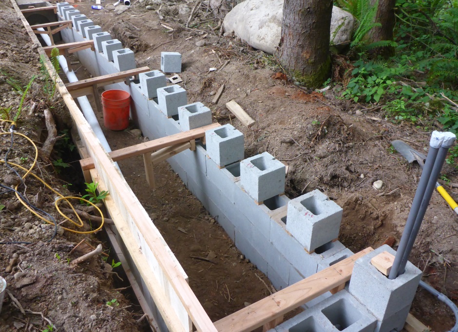
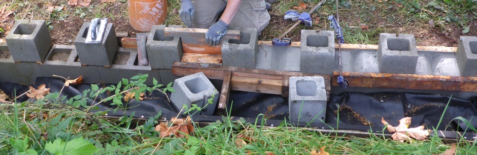
Build 3 courses of blocks (about 2' height, but measure exact height) that should leave the top 2" below the top of the catch basin. Use a self leveling laser throughout the block building process.
18" on center notches. Notches are 2" wide and 2" deep. Notches need to be V shaped.
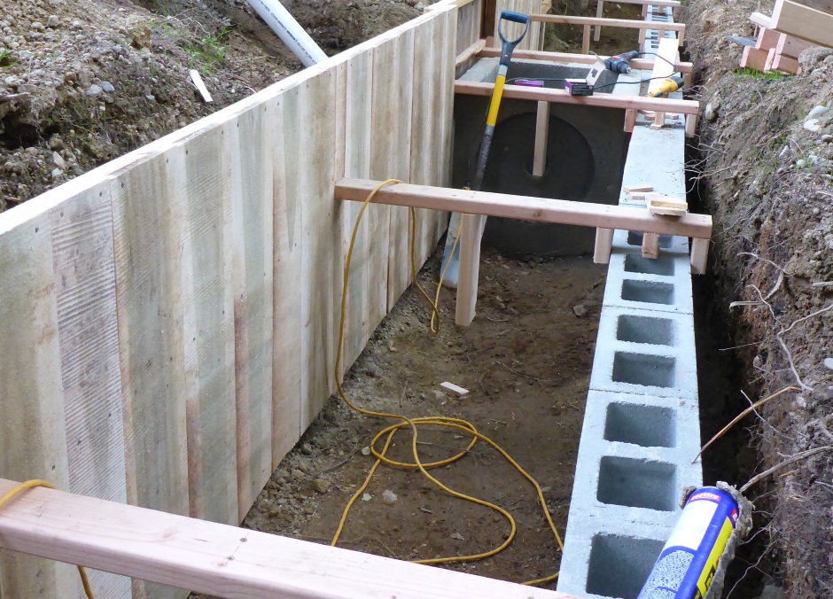
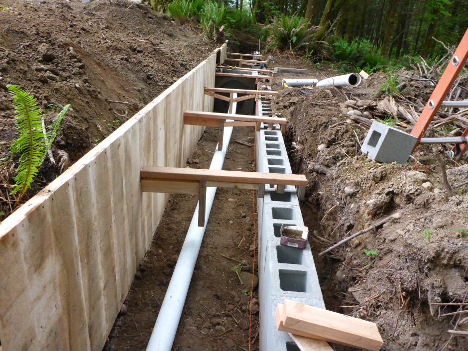
Build solid wall on downhill side of the trench up to 2" from the top of the catch basin. The layer of blocks above that has gaps between the blocks.
4" perforated pipe in the ditch with Wye cleanouts at each end and caps at each end. The pipe is exactly level.
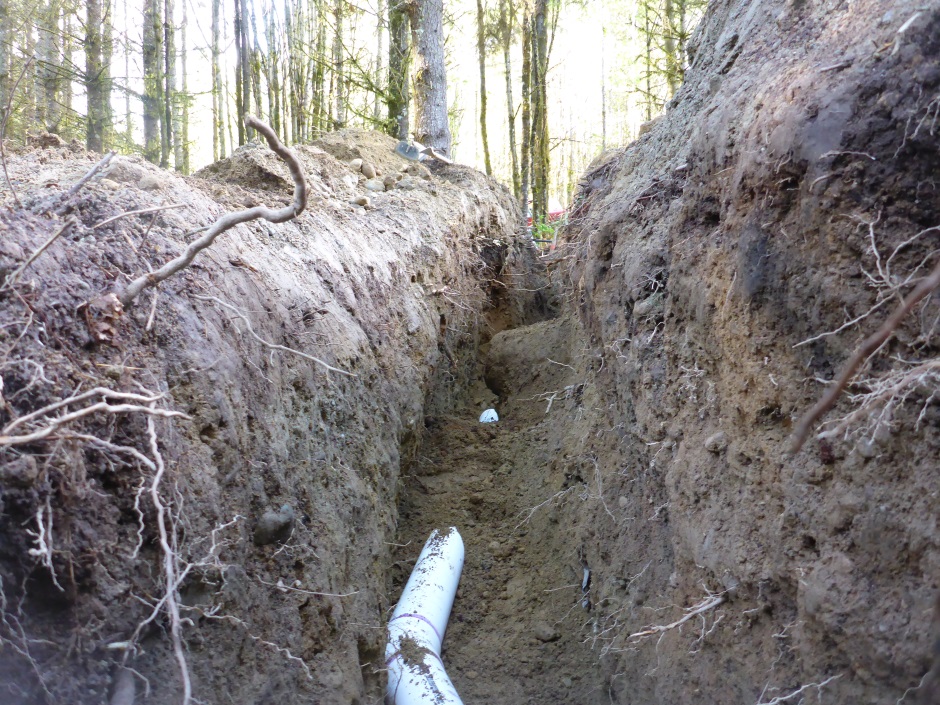
The ditch is lined with filter fabric and filled with clean 1.25" crushed rock.
Exact trench dimensions
Earth bottom 22.5" from top of catch basin
Earth width: 28.5"
(2'4.5")
Lined with filter fabric
4" perf pipes are level
Cleanout Wye at ends with separate end cap
Rock size: 3/4" -
1.5"
Notches 18" on center
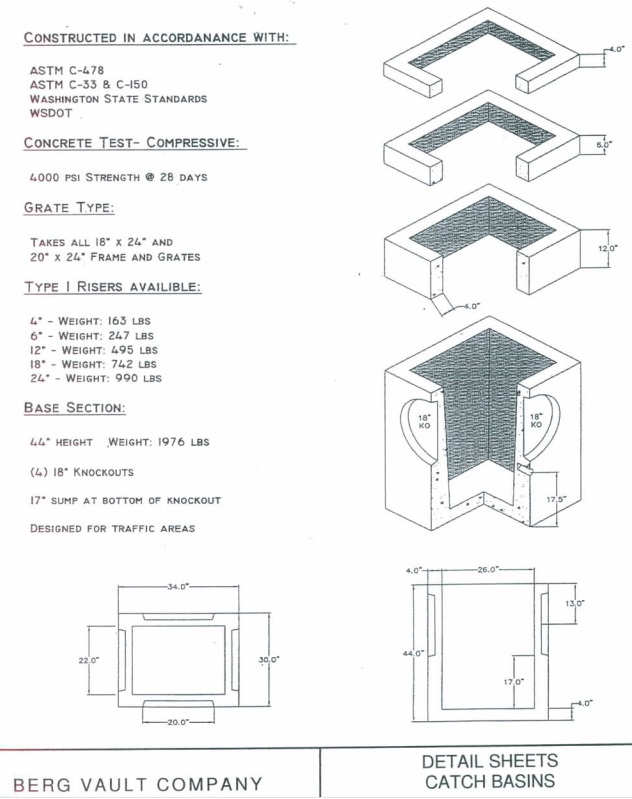
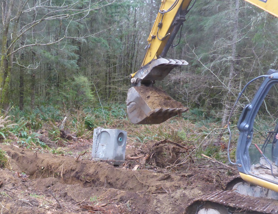
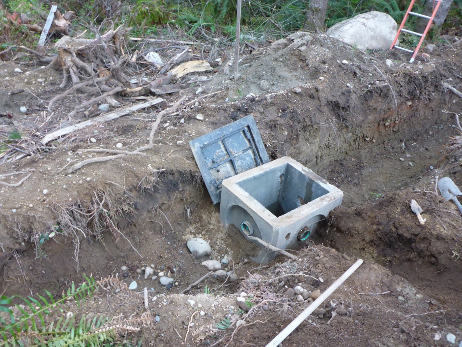
Catch Basin
Drainage plan specifies a "Type I Catch Basin".
Definition: An underground concrete water receiving inlet, rectangular in shape (approximately 3’6" x 2’6" x 4’ deep) with a slotted iron grate on top to inlet water or a solid rectangular cover. Water may also enter/exit through culverts visible in the side walls of basin. Invert refers to the lowest point of a pipe where it enters or exits a catch basin.
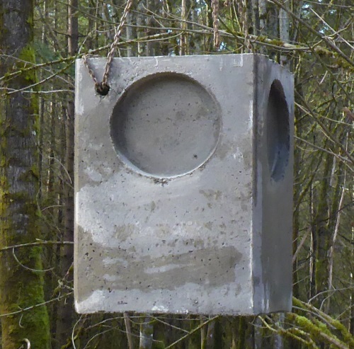
A suitable concrete Type 1 Catch Basin is available from Berg Vault
Company.
peggy@bergvaultinc.com
www.BergVault.com 2308 Cedardale Road Post Office Box 1205 Mount
Vernon, WA 98273
Swale
Here's the official drawing from the drainage plan (not to scale).
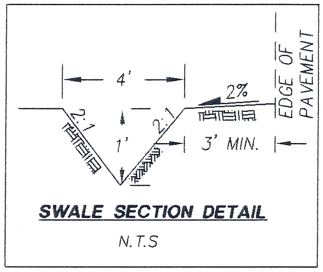
Swale along side of new driveway (2:1 side slopes, ie 30 degrees).
4' wide, 1' deep.
80 feet long.
The house earth wire will
go in the swale to keep it nice and wet en-route to well.
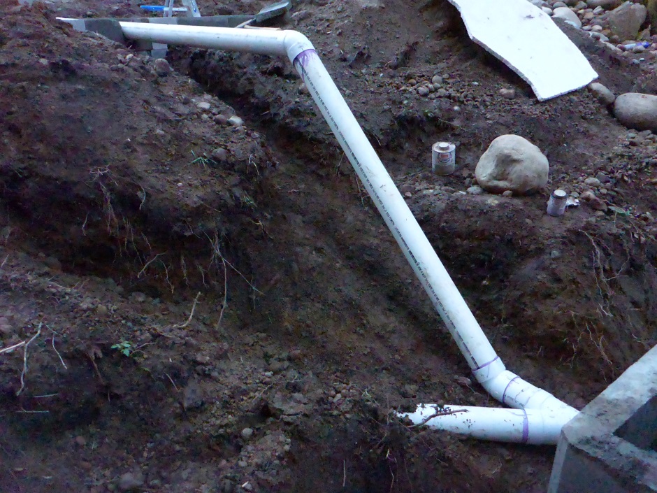
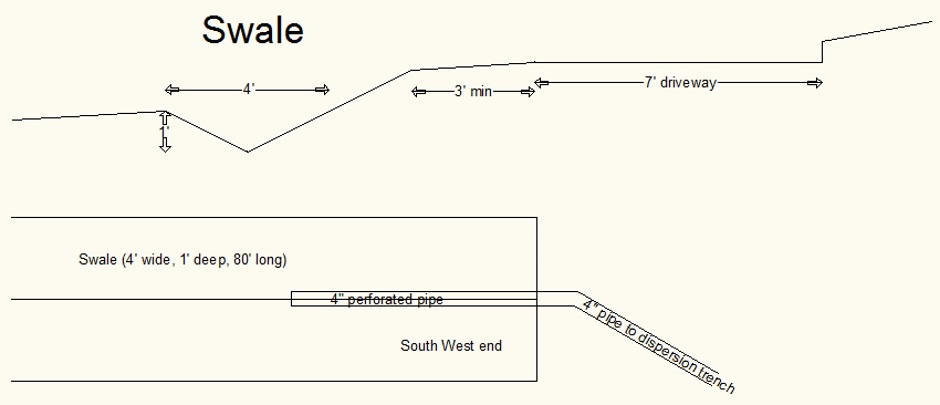
Here is the implementation drawing...
Rain storage tank (Retention Pond)
Storage for rain water is also on the drainage plan and so needs to be implemented. I could have got this removed from the drainage plan, but I wanted it anyway so that I had a rain water collection system for watering plants.
The top of the tank (the water input) needs to be at 10.5 feet below grade.
As well as providing you with a supply of harvested rain water, the tank also functions as what is known as a "Retention Pond". Retention ponds maintain a permanent pool of water throughout the year. They remove pollutants by allowing sediment to settle and through biological uptake, as plants absorb excess nutrients. Wet pond water levels can increase dramatically as a result of rainstorms. In my case, any excess water goes to the dispersal trench.
There is information from King County on how to beautify
retention ponds at...
http://your.kingcounty.gov/dnrp/library/1998/kcr745/intro.pdf
http://your.kingcounty.gov/dnrp/library/1998/kcr745/enhancement.pdf
http://your.kingcounty.gov/dnrp/library/1998/kcr745/casestudies.pdf
http://depts.washington.edu/uwbg/education/King%20County%20Raingarden%20Permit%20discussion%2010%2021%2013-2.pdf
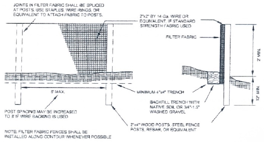
Silt fence
The following diagram is from the King County drainage manual...
Downslope of all disturbed areas.
Drainage plan shows some silt
fence that is not downslope from excavated area (to the east and
along existing wellhouse driveway). This may be a mistake on the
official drainage plan.
A better solution is to put silt fence from the wellhouse around
all of south to south east.
In practice the areas that are
actually exhibiting the possibility of silt runoff will be done
first. It is further proposed that the silt fence is only
actually needed while the soil is being disturbed and can be removed
after the drainage system has been implemented and grass has grown
back.
The silt fence goes at edge of build site area (where orange fence
is).
The bottom 4" of silt fence is buried and secured in a
trench. This prevents water undermining or bypassing fence.
The trench must be 4" deep and 4" wide.
Sediment buildup height
must be kept to less than 6".
Trench has 1-1/4" crushed rock (no
fines, washed) or Native Soil. (or perhaps rocks).
I use the rocks rescued from the excavated soil.
This nicely holds the bottom of the filter cloth.
Install along
contour where possible.
Posts 6 feet max apart or 8' if wire
backing used.
Posts can be 2x4 wood or steel or rebar.
I use fiberglass #4 rebar as it's easiest to bang into ground.
Use 3' long posts - 2' above ground, 1' underground.
Specifies 2"x2" galvanized 14 gauge wire fence (or equivalent) if
standard strength fabric is used.
Note that it
says "or equivalent" so this allows some implementation flexibility.
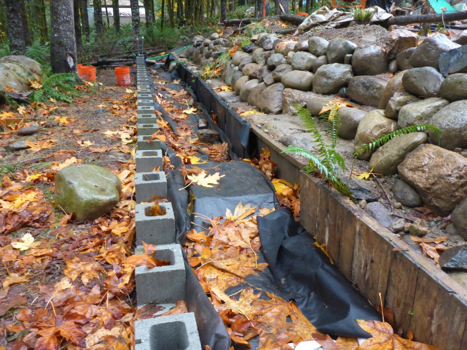
My implementation is...
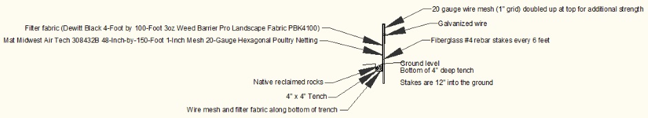
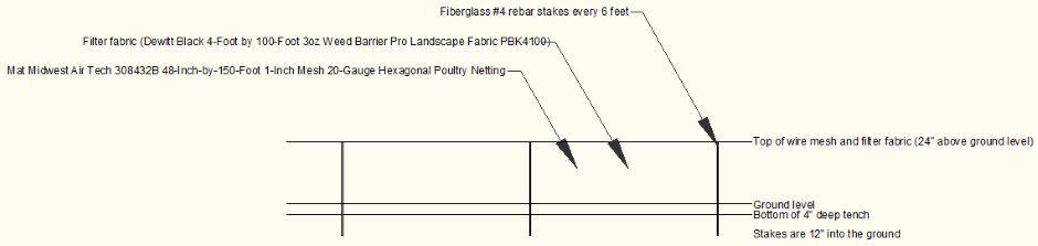
The filter cloth used is expected to meet the following specification.
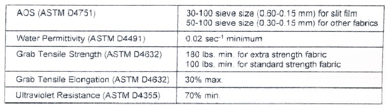
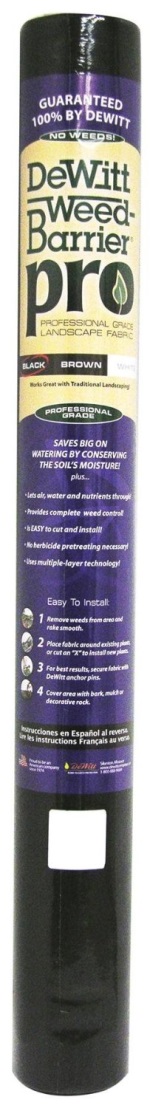
It is quite hard to get the actual specification for the filter cloth you purchase. I use "Dewitt Black 4-Foot by 100-Foot 3oz Weed Barrier Pro Landscape Fabric PBK4100", but I don't know for sure that it meets the above spec.
 Details
are here .
Details
are here .
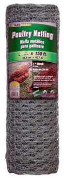
To support the drainage fabric, wire mesh fencing is required behind it. The official spec calls for 14 gauge wire with a 2" grid. I use 20 gauge but to compensate for the smaller gauge I use a 1" grid and fold it to double up the top 12".
 Details
are here .
Details
are here .
Construction Entrance
The official drainage plan calls for a rock construction entrance to be
constructed prior to construction on site commencing.
King County
notes say that a "stabilized construction entrance" is only required
if the entrance is within 1000 feet of a paved road. The fact
that the drainage plan calls for it is a mistake given that the
construction entrance is way more than 1000' from a paved road.
In practice there is already a crushed rock entrance that is more
than 100' long, so no further implementation is planned.
Existing driveway
The drainage plan says a 2 foot wide crushed rock
strip is required on the south edge of the drive. It does not specify rock size or depth.
I will add some more 1-1/4" crushed rock to driveway, slightly more
to the south side.
Soil protection
Straw over all bare earth during
construction (when not being worked).
Soil amendments shall be
applied to excavated/cut/filled areas. Compost is the main amendment
they seem to like but straw also counts as an amendment.
Once soil
is at final grade it must be seeded and have mulch (eg straw) spread
over it.
2 or 3 bales of straw per 1000sqft of bare soil.
I estimate
our mountain and grade area is about 10,000 sqft so that means 20
bales.
Top soil store
The drainage plan forms specify that I am required to have a stockpile of 700 cubic
yards of top soil.
Much of the top soil has already been put back
on areas that are at final grade so the actual amount still in the
stock piles is reduced.