


Home Site Map - Steps - Foundations -
Foundation Rebar - Key Notch Etc
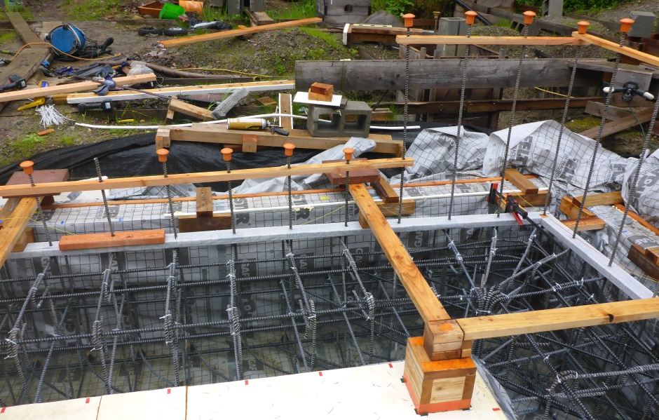
![]() It is necessary to have good mechanical keying between the walls and
the slab.
It is necessary to have good mechanical keying between the walls and
the slab.
Form top groove
Key notch plank
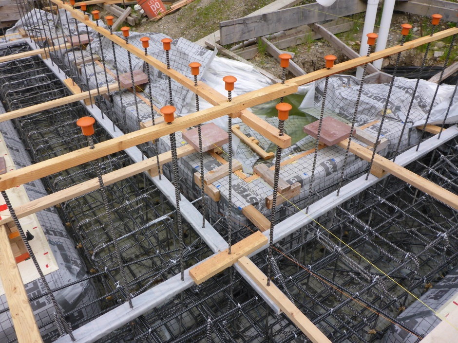
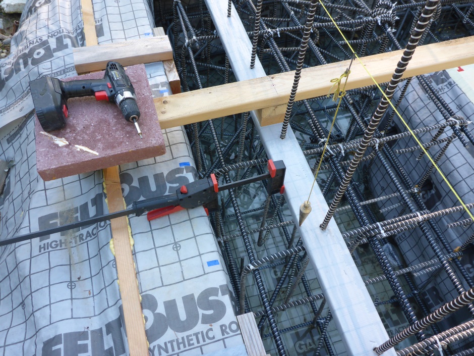
The 3.5" groove is formed by lumber cut to 2.5" x 1" with half inch EPS glued on the bottom and sides. They are also as a final step wrapped in tough-liner (use staples on the seam at the top). The EPS makes it easier to remove after the concrete has set. The 3/4" holes in the planks hold the vertical rebar in the right place.
Cut the 2.5"x1" wood from lumber that is 8' long. You can get two pieces from a 2x6. Join the planks together using a couple of 1/4" wood dowels in the end and some PL-Premium. Arrange the bow of the planks such that the joins are the highest point and the bow is down in the middle.
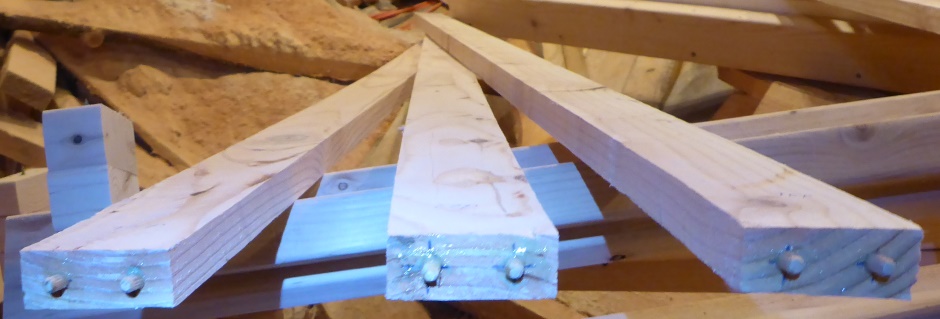
A jig is used to glue the EPS to the outsides.
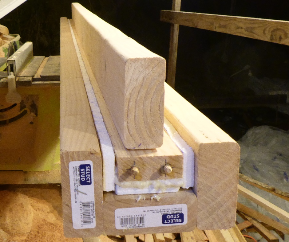
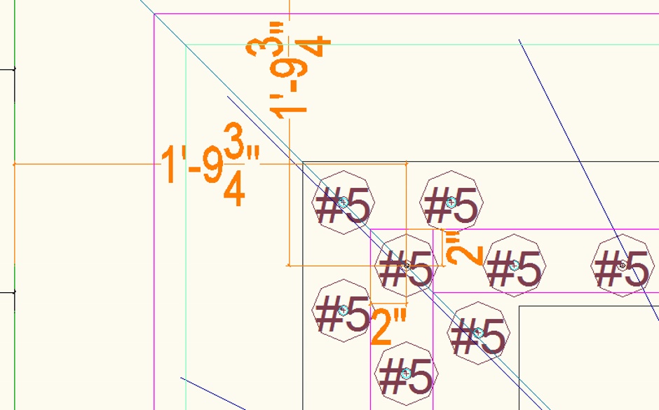
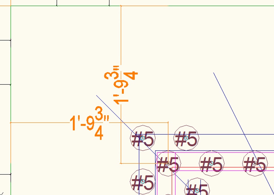
For both the external and internal footings, the 3/4" holes for the vertical rebar are not in the center of the planks. There is 2" of plank on the outside and 1.5" on the inside.
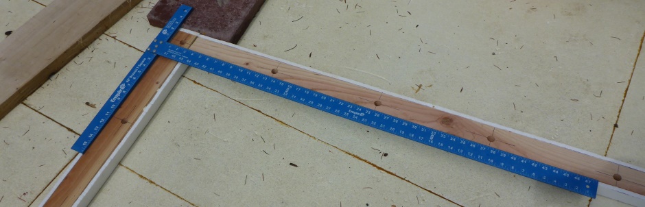
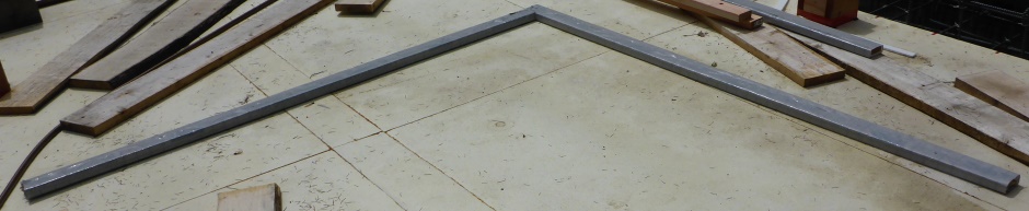
Start by making the corners (as these are the starting point for measuring the rebar hole positions).
Join by drilling holes for the dowels in the side of a second plank. Glue the corners with PL-Premium. Use a T-square to get it a true right angle.
Once the glue has set, drill 3/4" holes in the groove planks to correspond to the vertical rebar positions, which are 12" on center.
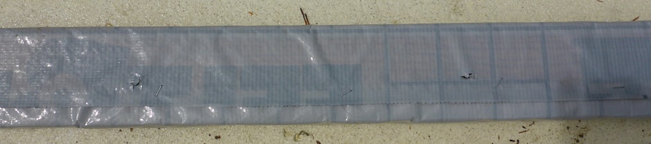
Wrap the groove planks with tough-liner as this all helps to make them easier to remove after the concrete pour. After stapling, cut a cross at the hole position in the tough-liner to let the rebar go through.
Fit the corners over the rebar first
This is typically a 2 person job.
Fit straight groove planks
In addition to the two dowel pins, glue then together with PL-Premium. Make sure they are tightly together (so the assembly is not artificially long). Use a clamp to pull them together (with a temporary screw in the side of the groove plank). To strengthen the join use a 20" long piece of 2x4 screwed on (with a hole for the vertical rebar).
Internal walls
Need the grove plank on the internal concrete walls too. Note that there is a 1.25" offset relative to the plank on the outer footing.
It is often helpfull to use bits of spacer wood to get the groove plank the right distance from the outside.
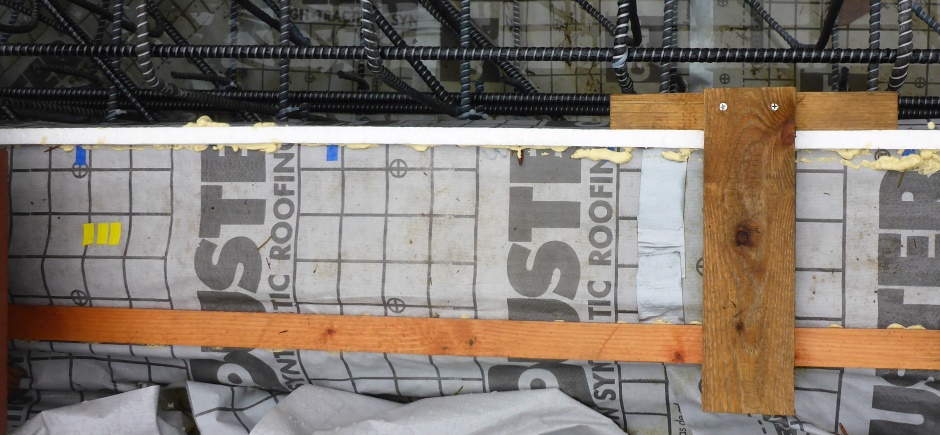
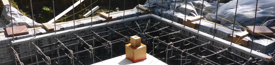
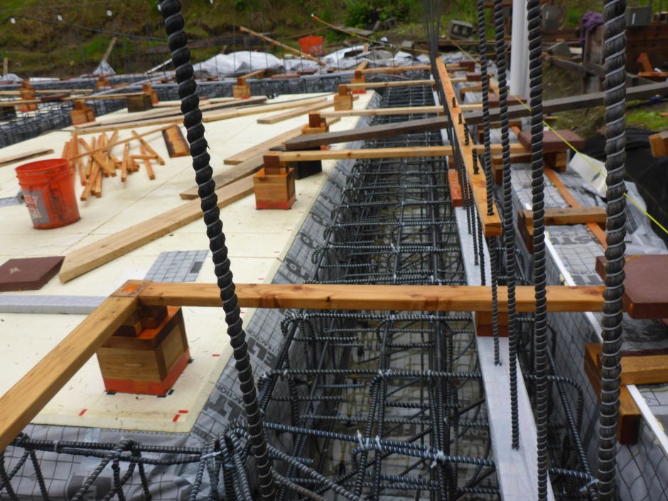
Having the key notch lumber in place while pouring the concrete is useful as it will help show the required concrete level. The top of the planks will be at the same height as the outer Form-a-drain and the wood cubes.
In order to take out bow in the groove planks it may be necessary to attach on edge 2x4s to the middle of the top side. These are attached with just 2 screws so they can be removed for final screeding after the concrete is starting to harden.
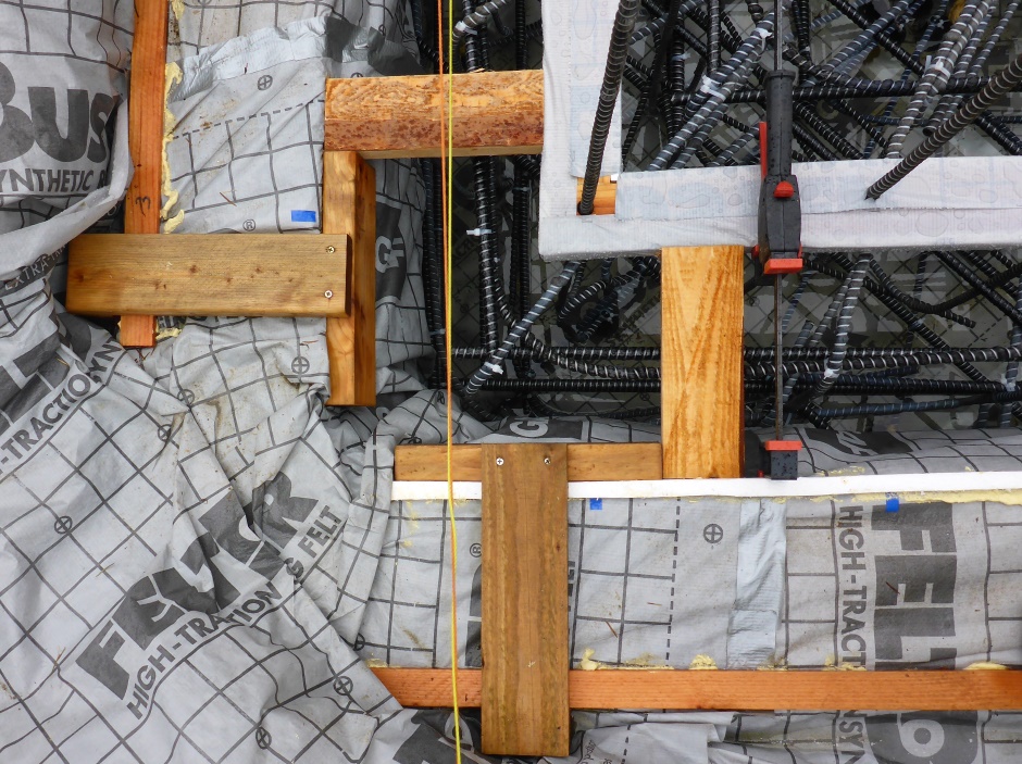
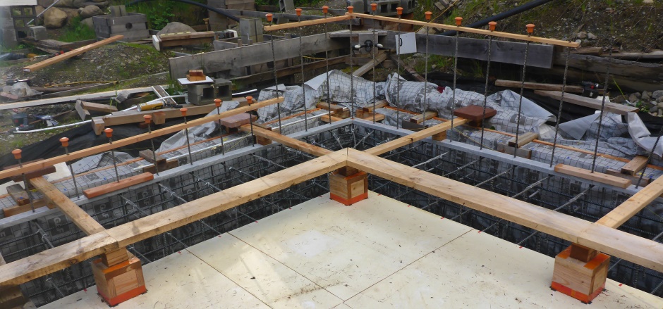
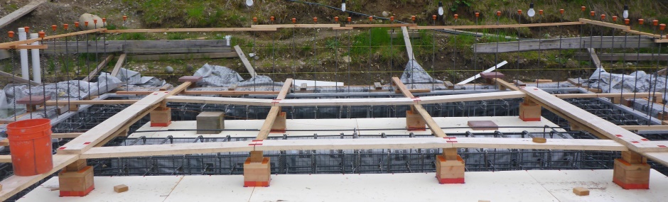
Cross trench jigs
About every about 6 feet there is a 2x4 assembly across the footing trench. It hooks over the outer upper form-a-drain. A 12" paving slab is used to keep it weighted down. At the other end it is supported by an 8" wooden cube that sits within the rebar grid on the slab area. The cross trench plank supports the groove notch plank that has 1 foot pitch holes for the vertical rebar.
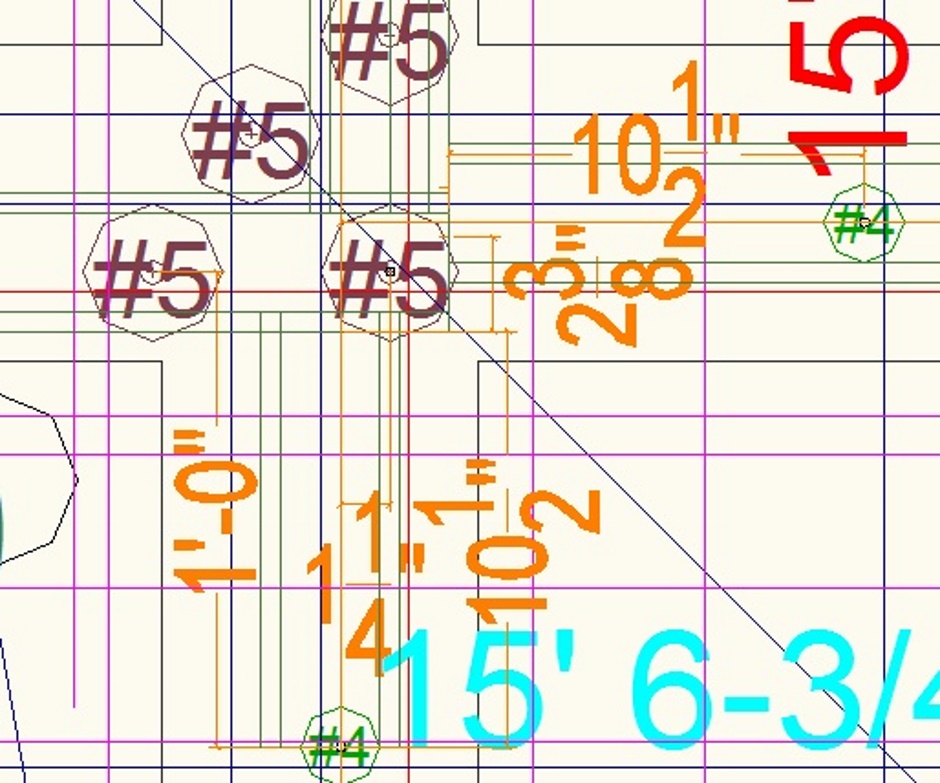
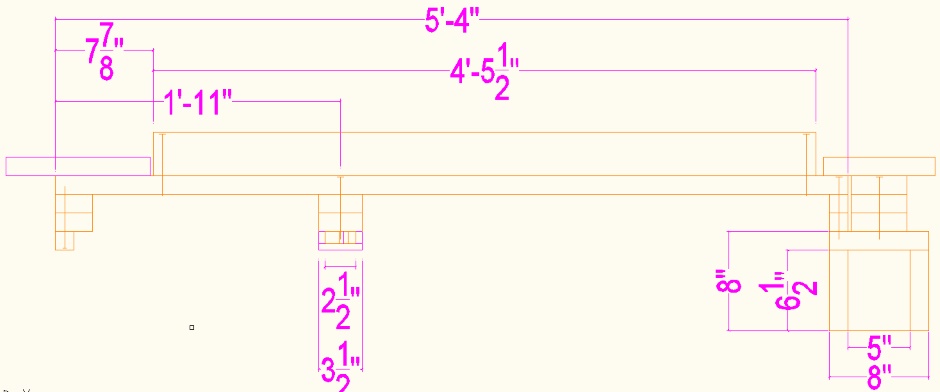
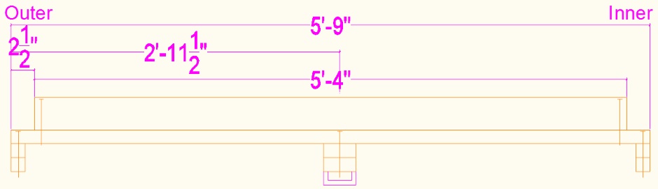
Here's the drawing for the most common jig type that is used on the outer footings. In my case I need 34 of these.
5' 4" Outer footings 34 off
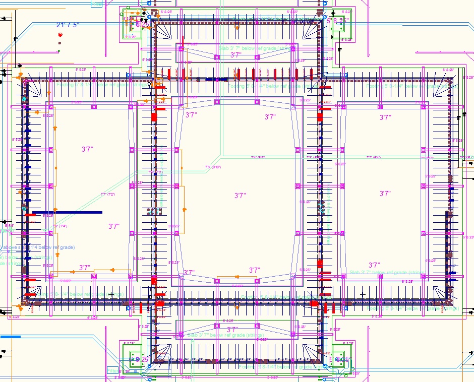
Where possible it is good to stick to standard dimensions for the jigs that support the groove planks, but in some cases they need to be non standard to ensure they don't conflict with the rebar positions. Also making some non-standard allows the number of 8" cube boxes to be minimized. Plan it out on your AutoCAD drawings.
Here are the other jig drawings.
6' 6" Outer footings portico middle 4 off
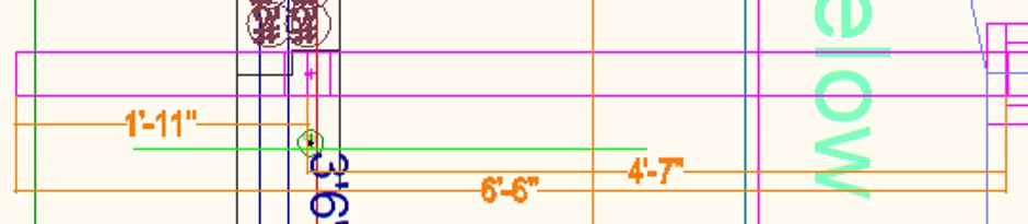
5'9" Internal footings 10 off
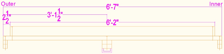
6'7" East west internal at corners 4 off
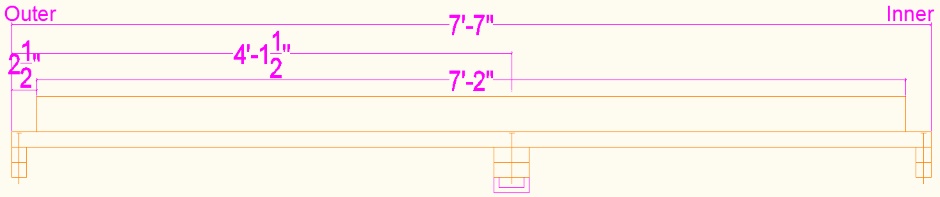
7'7" North south internal at corners 4 off
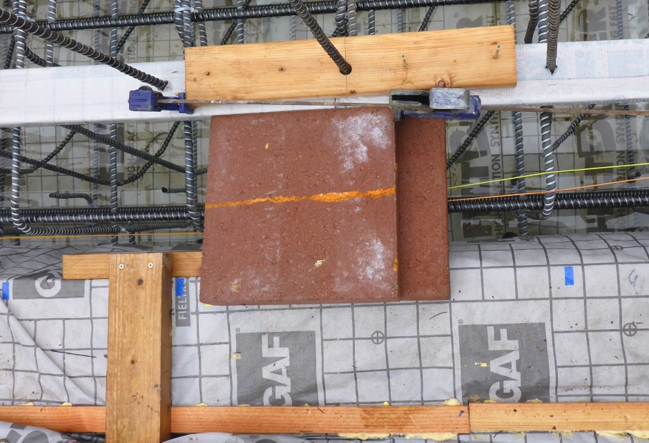
Add paving slabs
At the form-a-drain end of each cross trench jig add a 12" square paving slab to keep the end resting tightly on the top edge of the form-a-drain.
Screw cross planks to groove planks
Set the position using a plumb-bob from a string off the batterboards. Set the string to be the outside position of the groove plank which is 2" further out than the center of the vertical rebar.
A "pusher" wood clamp or a "puller" wood clamp can be used to adjust the position of the groove plank so that the edge lines up with a plumb-bob off the batterboard string.
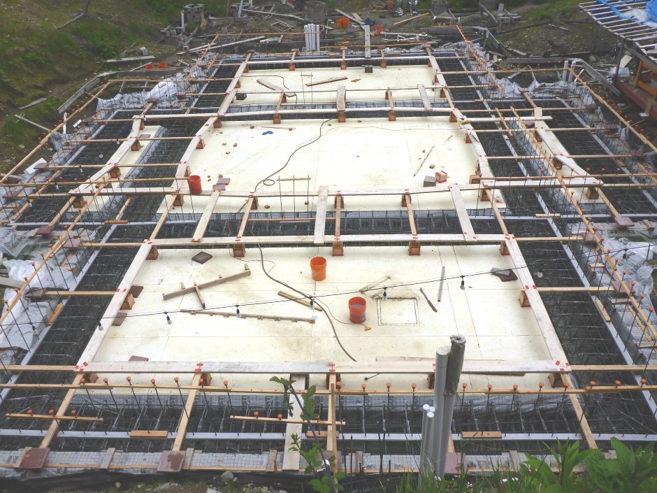
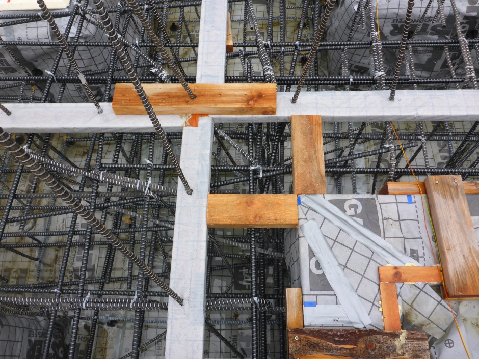
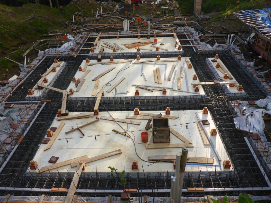
Walkway system
This walkway system will stay in place even while doing 90% of the concrete pour for the foundations. It consists of 8" wide planks between the 8" wood cubes. It is designed to not get in the way of the rebar that will be over the slab. The planks get screwed to the wood cubes (2 screws each end) and thus ensure that the cubes do not move and thus the groove planks do not move. The lengths of the planks are as per your AutoCAD drawing.
Put tape over the screw heads so the heads do not get clogged with concrete. The planks can be removed as needed during the concrete screeding.
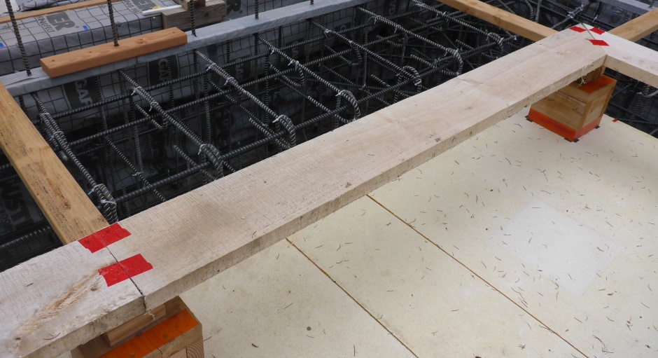
The 8" high blocks will stay in place during the concrete pour and concrete setting. The screeding is done off the top edges of the 8" high wooden cubes. The holes in the slab left will be filled with bagged concrete later.
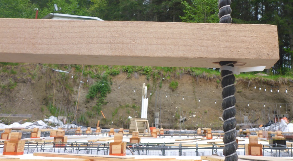
Stiffening and adjusting
This is an optional piece of 'on-edge' 2x4 screwed on top of the cross trench jig. It stiffens the jig and provides height adjustment.

Use a self leveling laser and a length of white pipe to get the key notch plank height exactly right. Use wood shims under the stiffening 2x4 to adjust the height of the groove plank.
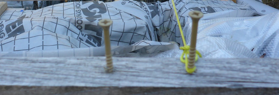
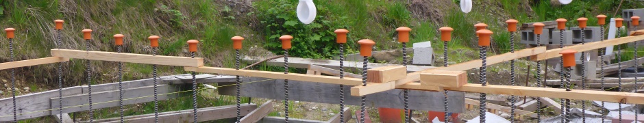
Sticks to hold top of vertical rebar
The sticks are about 1.5" square with 3/4" holes in the right places (typically 12" on center).
Stop the sticks falling down using a few cable ties on the vertical rebar.
Fit rebar safety caps
Adjust vertical rebar height
The vertical rebar is currently not specifically tied but rather is relying on friction with other rebar, together with the groove planks, to hold it in place. Potentially the tops of the vertical rebar will be at different heights. Use a self-leveling laser to set the tops of the vertical rebar to be...
3' 6-1/2" above slab height for long vertical rebar (1'
6-1/2" above batterboard laser height)
1'
6-1/2" above slab height for short vertical rebar (5-1/2" below
batterboard laser height)
EPS strip to stop concrete overflow
This is optional and in practice is not required. If the EPS area around the outside of the external footings is a little low then a thin layer of concrete may cover it. This thin layer of concrete is not a big problem. The membranes go outwards so there is no danger of a sharp concrete edge puncturing the membrane.
If you really want to stop it then you can add a thin shim of EPS.