


Home Site Map - Techniques - Structure -
Carnation Walling - CAD Drawing
![]() Use accurate drawings all the way through the build process are
vital.
Use accurate drawings all the way through the build process are
vital.
Get everything marked up on your CAD drawing
Make your CAD drawings correct
Things will go wrong very quickly if you measure and cut as you build. All cutting and positioning of things needs to match exactly with the CAD drawing. If something does not match then find out why before proceeding. The CAD drawing needs to show all the tie positions through the concrete, and even all the bracing, including where the angled bracing attaches to the floor. Getting the CAD plan drawing correct is very important. With things like bracing it is sometimes necessary to joggle things about a bit to get everything to work out and it is so much easier doing this in a CAD app rather than on site.
Allocate plenty of time to updating your CAD floor plans with this info. Read through the steps below and as you imagine yourself doing each step, update the CAD drawing. In your mind, build it in CAD first.
Here is a drawing for a very simple building (suitable for a plant potting shed in the yard)...
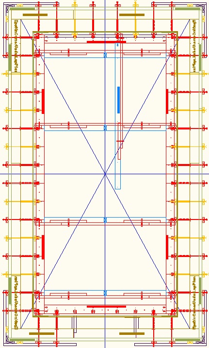
It does take a bit of practice and experience to allocate the EPS sheets (and plywood sheets) to the desired building footprint, but I have tried to write down the rules below. If you need me to do you a CAD drawing for your house then I can, but a fee will be involved as it is rather time consuming.
Add Wall section center markers
Start by drawing the blue lines to divide the building into 4 quadrants. The halfway measurements are from the outside of the concrete wall (the outside of the concrete is the reference line). However complex the building, there should be only one north/south east/west cross, centered on the center of the building. You start figuring things out from the center of the building and work your way outwards. Add-on "concrete rooms" round the outside are handled separately rather than having their walls divided in half.
Diagonal lines for squareness
Draw the diagonals (blue/purple lines) to the wall reference so that when on site you will be able to check the right-angles of the walls drawn on the slab are correct.
Add-on concrete rooms
If there is a U shaped piece of concrete wall used to add-on a room, the join to the main building will not anyway be able to use standard blocks, so there is no point in calving up the room with wall section center points. Just use the outside concrete of the convex corners of the U as the reference when doing the 1' markers described below. The room will typically still be divided in the other dimension by the building's divider cross. I use this technique for the east and west concrete sections of the house and also the add-on portico bases in the basement.
Internal walls
It is best to treat internal concrete walls as external walls within the internal room that they form. Use the outside edge of the concrete as the reference for the 1' markers.
Treating internal walls as if they were external walls means that other concrete rooms are handled as add-on concrete rooms.
Internal walls do not use any EPS. They have the twin plywood on both sides. There is a nailed down kicker board on both sides.
It is only necessary to have angled bracing on one side of internal walls and it is best to put that bracing on the inside of the internal room that they form.
Odd and even 1 foot markers
Draw the 1 foot markers starting at the convex corners of the outside wall concrete of the inner-most concrete room. Identify the 0, 2', 4', 6', etc points as "primary" points (make those marks red). Make the markers at 1', 3', 5', 7', etc be "secondary" markers (make those marks blue). Follow the same process (starting with outside corners) when you add the markers along the wall for the add-on concrete rooms.
Concave corners
In terms of the wall tie hole pattern there is no special handling for a concave corner because of the concept of add-on rooms. The pattern will have come from the outer convex corner and the EPS sheets just get cut at the required point to fit into the concave corner.
Angled wall braces
Angled wall braces should only ever be at the primary markers (the red markers). Typically they go about every 6 feet. You can move them to different primary markers and that is sometimes useful to avoid clashing with angle braces from the adjacent wall.
Sometimes you can leave out an angle brace if the EPS will be overlapped with a perpendicular piece of EPS that will naturally hold it vertical. Just because there is no angled brace at a particular location does not mean that there isn't still a vertical 2x4 baton that is held vertical by the horizontal bracing.
EPS at building centers
At the building center cross points (as the blue cross intersects a wall) it is necessary to arrange for the joints to be next to a suitable odd numbered (secondary) 1' grid point so that it has a vertical 2x4 baton over the join. It is necessary to use custom cut and drilled blocks. Different secondary marker points are chosen to join the 6" EPS compared with the 2" EPS.
Unless the center point happens to fall on a marker point (unlikely) then the drill pattern changes when going past a building center point. It is good to have at least one column of wall ties each side of the joint, so that means custom drilling of hole columns is necessary. You still will want to keep to the rule of the first column of holes being 1" from the edge (offset towards the corner).
If the distance that needs to be spanned between standard blocks exceeds 8' (the max length of a sheet) then you butt the join 1" from a red primary marker. This avoids it being on a join for the row above. For a very long span you might need two joins next to red primary markers.
12" cavity corner wall tie offset
At corners in the case of 12" cavity walls it is necessary to adjust the wall tie placement by 4" relative to the 1' regular grid. This means the holes in the EPS need to also be offset by 4". Also the the horizontal bracing is 4" shorter at the corner end.
2nd and 4th EPS row version
The initial working out of EPS sheet lengths is done for the base row of EPS that goes on the slab. This is also the configuration used on the 3rd row. The 2nd and 4th row use a different configuration so as to produce a staggered brick pattern. It is necessary to do a different version of the CAD drawing that shows the EPS sheet lengths for the 2nd and 4th rows. Everything else about the CAD drawing (including all the bracing etc) all stays the same.
Bracing for bucking
Bracing is used to support the inside edge of the window bucking long before wall concrete is poured and even before the wall rebar is added.
There is always an internal vertical 2x4 baton near each side of a window or other wall opening. It attaches to the Cavity Bucking top and bottom using 3" wood screws (and some wood blocking for added strength). The internal vertical 2x4 batons are always on the odd numbered secondary 1 foot markers so they don't interfere with the wall bracing. They will likely not be symmetrical on the window but that's ok. Make the internal vertical 2x4 batons offset in the direction determined by the nearest corner of the complete building.
The internal vertical 2x4 batons for the windows are in addition to the internal vertical 2x4 batons for the walls. When doing the CAD drawing, add the batons and angle bracing for the wall openings in addition to the angled bracing that you will already have added for the wall using the normal rules. The presence of windows, doors, or other wall openings does not reduce the amount of wall bracing or its placement.
Between the two ends of the bucking add internal vertical 2x4 batons at two of the secondary locations. This is to help support the weight of the bucking. Note that the bucking needs to be supported even if the wall bracing is not fitted. The bracing for the bucking starts in its final position rather than in the concrete cavity position.
Elevations and window door openings
In the CAD app, onto the elevation drawings, copy on the standard block elevation library shapes. Use all the rules described above. Make sure it all matches with the plan drawings. Where a standard block will not fit, draw the cut shape with regular lines (using the 2" or 6" EPS CAD layer). Draw on the window and door openings. Do it for the 6" and 2" EPS.
Once all done, turn off all layers apart from the 6" EPS layer and then turn off all layers apart from the 2" EPS layer.
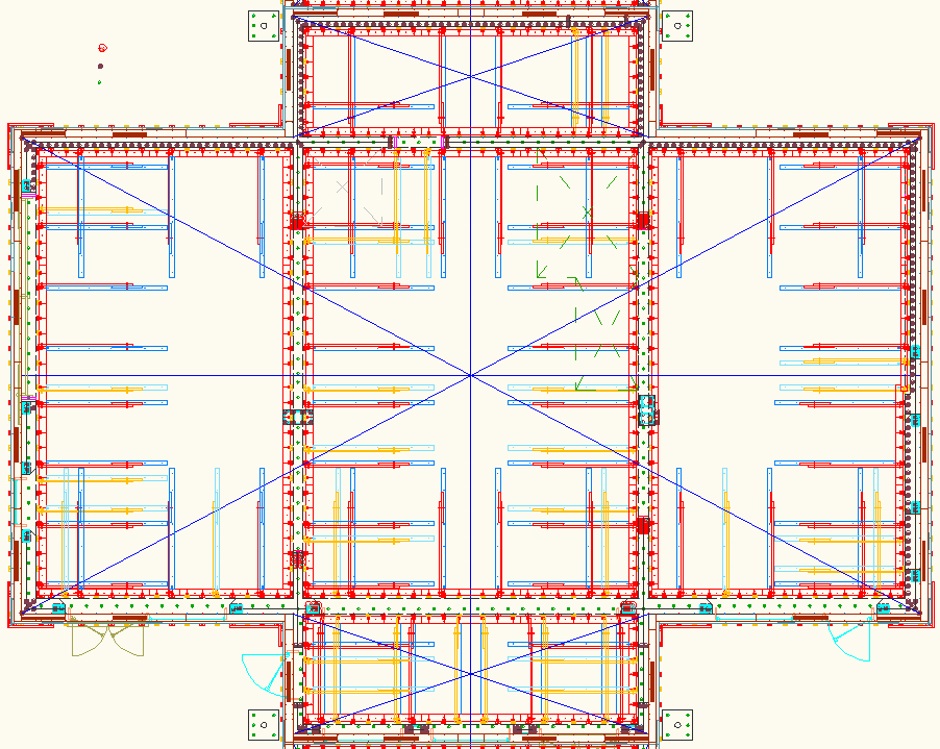
Real CAD example
Here is the CAD drawing for my basement level. It is quite difficult to remember all the rules stated above so it is not a bad idea to take this drawing as a starting point and modify for your own particular house design. (It's better looked at in the CAD app as that also let's you get dimensions of the EPS sheets.)
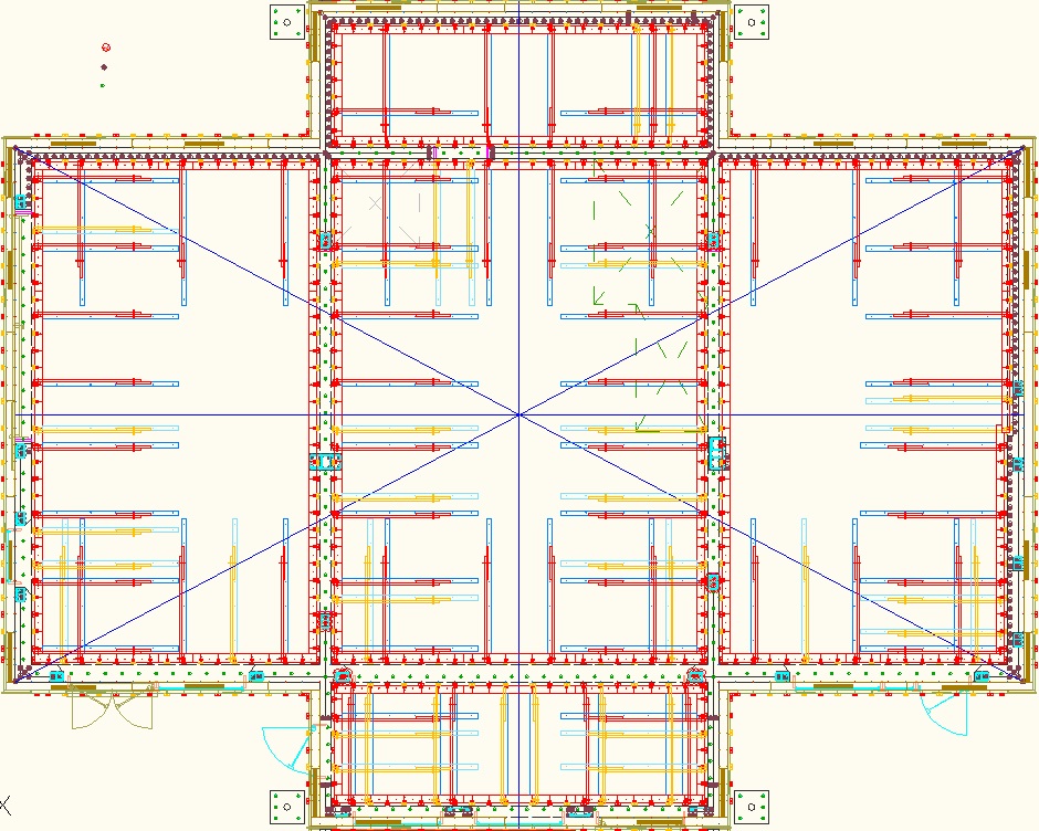
Note that the EPS sheet lengths shown are for the base row of EPS that goes on the slab and also for the 3rd row. The 6" EPS is 4' high and the 2" EPS is 2' high on the base row. The row above has different lengths in order to produce the staggered join pattern (and both the 2" EPS and the 6" EPS are 4' high sheets).
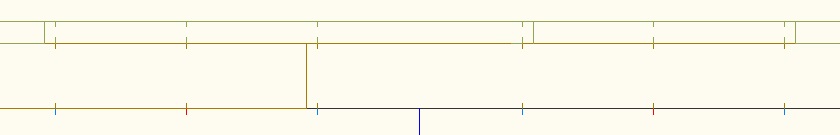
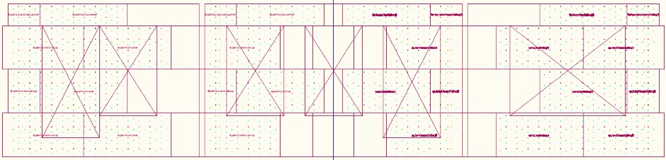
Here is the CAD version for the 2nd and 4th rows (it's better looked at in the CAD app and that also let's you get dimensions of the EPS sheets).
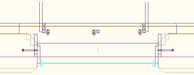
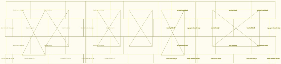
Here are the CAD drawings that show the window and door openings for the south elevation as well as the tie rod positions.
Buy the materials
The house is built one story (ie one level) at a time, with the concrete ceiling of the house level being done at the same time as the walls for that floor. For each story you need to buy enough 6" and 2" thick EPS sheets for the walls including the portico bases and also buy the Carnation Flooring EPS for the ceiling above. Here's the list of parts needed...
EPS sheet (6")
EPS sheet (2")
1/2" electrical conduit (10'
lengths)
3/4"
electrical conduit (10' lengths)
3/8"
threaded steel rod (10' lengths)
3/8" steel zinc plated nuts
3/8" large steel zinc plated washers (about 1" diameter)
Corrosion Proof Large Washers with 3/8" hole
8'x4' plywood 15/32" thick
(Nominally 1/2")
8'x4' plywood
3/16" thick (Nominally 1/4")
Foam adhesive
Foam gap filler
2x4
lumber
Rebar cable ties
11" (65 lb)
Basalt
Rebar
Carnation Flooring EPS cut forms